The Hypex data sheet is attached, look at General Performance Data, Output Voltage Main, Note 1.I don't dispute any of that. I just don't believe they run it open loop.
G²
Attachments
Thank you for all the people who have contributed ideas and comments! Helping me learn about linear power supplies.
Here's my parts list along with questions:
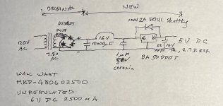
1) Filter cap: limited by size constraints. I have 2 choices, a 8100µF 25V or a 10000µF 16V (EKYC160ELL103MM25S) Al electrolytic. I am guessing that a higher voltage rating will lend itself to a longer lifetime. I am leaning to the 10000µF one because it will reduce the ripple voltage by 20% into the regulator. Comments?
2) Regulator: BA50DD0T 2A, LDO model. Will get a TO-220 small Al heat sink. Question - should I ground the heat sink or leave it floating since nothing is actually electrically connected to it?
3) Input cap: It will be soldered very near the regulator The application notes say minimum .33µF. I have a choice between a .33 and a 1µF, 50V ceramic (C420C105K5R5TA91707200). Question: Why shouldnt I use the 1µF cap? Size is about the same.
4) Output cap: For stability I choose around a 2 ohm ESR. Ta capacitor, 22µF, 10V, 2.7 ohm ESR (TAP226K010CCS). Its only 50 cents more than an Al.
5) Diode to prevent surge when unplugged: This one I do need some help. The choice is small for axial didoes. A 1N5401 diode has a leakage current of 5µA and a Vf=1V. Dont know if this will work. Shottky diode I found one with .5µA leakage and Vf=.85V. I read that Shottky diodes are not as robust as regular diodes, so I would prefer a 1N5401 if it could work. Comments?
Thanks again everyone! Will include some pics, before and after when I am done. Total cost excluding wall wart is under $10.
Here's my parts list along with questions:
1) Filter cap: limited by size constraints. I have 2 choices, a 8100µF 25V or a 10000µF 16V (EKYC160ELL103MM25S) Al electrolytic. I am guessing that a higher voltage rating will lend itself to a longer lifetime. I am leaning to the 10000µF one because it will reduce the ripple voltage by 20% into the regulator. Comments?
2) Regulator: BA50DD0T 2A, LDO model. Will get a TO-220 small Al heat sink. Question - should I ground the heat sink or leave it floating since nothing is actually electrically connected to it?
3) Input cap: It will be soldered very near the regulator The application notes say minimum .33µF. I have a choice between a .33 and a 1µF, 50V ceramic (C420C105K5R5TA91707200). Question: Why shouldnt I use the 1µF cap? Size is about the same.
4) Output cap: For stability I choose around a 2 ohm ESR. Ta capacitor, 22µF, 10V, 2.7 ohm ESR (TAP226K010CCS). Its only 50 cents more than an Al.
5) Diode to prevent surge when unplugged: This one I do need some help. The choice is small for axial didoes. A 1N5401 diode has a leakage current of 5µA and a Vf=1V. Dont know if this will work. Shottky diode I found one with .5µA leakage and Vf=.85V. I read that Shottky diodes are not as robust as regular diodes, so I would prefer a 1N5401 if it could work. Comments?
Thanks again everyone! Will include some pics, before and after when I am done. Total cost excluding wall wart is under $10.
The Hypex does indeed do what you say. Why anyone would WANTThe Hypex data sheet is attached, look at General Performance Data, Output Voltage Main, Note 1.
that is a mystery to me. Any power amplifier running off that will vary
the power output by the square of the ratio. I can put up with that but
it's not a desire but a necessity. To each their own. Thanks for the info.
G²
OK. Assembled and tested. Worked great! Exactly 5V out, with my load (Wiim Pro Plus) didnt get hot.
Since no one responded to my questions, this is what I decided to gte:
1. 10000 µF 16V cap. Its pretty big, so it was about 1.5" away from the regulator so
2. 1µF ceramic cap near regulator
3. BA50DD0T 2A, LDO with 4W TO-220 heat sink. Turns out that thermal considerations were a limiting factor in that I could only fit a small heat sink. 1.5A x (7.3-5V) = 3.5W That means with just convection, it will reach 120 °C max, which is just below the 150°C thermal limit. Custom enclosures can use custom heat sinks.
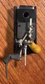
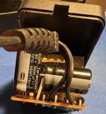
4. i connected the Schottky and antioscillation 22µF cap directly to the pins of the regulator since I ran out of places on the circuit board.
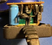
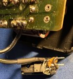
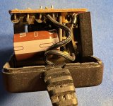
Pictures attached, first 2 are the original wall wart - the cap was leaking.
Next pic is the regulator with the diode and cap soldered to the pins. (Waiting for the M3 screw to be delivered)
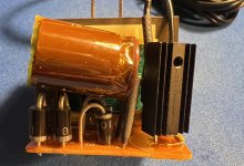
Last 2 pics are the reassembled board. This started out as a 6V, 2.5A wall wart, unregulated
Since no one responded to my questions, this is what I decided to gte:
1. 10000 µF 16V cap. Its pretty big, so it was about 1.5" away from the regulator so
2. 1µF ceramic cap near regulator
3. BA50DD0T 2A, LDO with 4W TO-220 heat sink. Turns out that thermal considerations were a limiting factor in that I could only fit a small heat sink. 1.5A x (7.3-5V) = 3.5W That means with just convection, it will reach 120 °C max, which is just below the 150°C thermal limit. Custom enclosures can use custom heat sinks.
4. i connected the Schottky and antioscillation 22µF cap directly to the pins of the regulator since I ran out of places on the circuit board.
Pictures attached, first 2 are the original wall wart - the cap was leaking.
Next pic is the regulator with the diode and cap soldered to the pins. (Waiting for the M3 screw to be delivered)
Last 2 pics are the reassembled board. This started out as a 6V, 2.5A wall wart, unregulated
Attachments


Comments to other postings
- I got this wall wart from ebay, but noticed Jameco sells them now as well, new. Since this was an experiment, wanted a cheap part to try
- I thought about using this circuit after a 8V switching supply as someone suggested. The main reason i did not was because I was trying to keep the parts cheap, and I was surprised how much enclosures were. I would need a enclosure, 2 jacks, a perf board in addition to these parts, so I decided against that route. This is probably a lower noise design as well, as regulators go down in rejection with frequency.
- Same reasoning for open frame and encapsulated power supplies. Finding an enclosure, putting in an AC jack and output jack would be costly and bulky.
- The limiting factor in this design comes down to how big a heat sink that will fit. If I used a 8V supply, I would have to be able to dissipate over 4W via convection, requiring a larger heat sink.
- If I had a variac, I would test how low in AC voltage that this would go. As is, it should work minimum 108V AC and nominally down to 105V AC according to my calculations
- It was fun, got to learn about linear supplies. I got another one off of ebay that was 5V, 1.2A regulated. Opened it up and the circuit was unusual. Had a BUZ10 MOSFET on a large custom heat sink, 2 other transistors, lots of resistors to do the regulation. The transformer was only 7.5V AC, so this design was an even LDO. It measured 5.2V DC out. Googled, and didnt find any design like that
- The most expensive parts were the 10000µF cap and the LDO regulator, about $3 each. Remainder was under $1 each. Total parts was under $10. Wall wart was $12, so total was $22, much cheaper than a 1.5A 5V linear power supply online.
Last edited:
3) you can use bigger than 0.33. In the datasheet they mention the minimum for stability. Choice of ceramic is ideal so 1uF is perfect.
I was looking next if if was possible to use the 5V wall wart, and discovered an error in my calculation:
Vsecondary transformer= (Vout+Vreg+Vrect+Vripple)/.92 x (Vmain/Vmainmin) x .707
= (5 + .7 (LDO BAxxd0) + (4 x .7) + .62)/.92 x (120/112.8) x .707
The error is the forward voltage drop in the rectifier. Since the current only goes thru 2 diodes each wave, it should be 2x not 4. Also the forward voltage drop I used was nominal, and for a 1N5401, it is listed as 1.2V in the data sheet. So the corrected number is 7.1V min for the AC voltage required, which makes it even better, as the 6V wall wart had a 7.8V AC voltage.
Now, the 5V wall wart has a AC voltage of 6.2V <7.1V so this wont work.
I discovered that there are Schottky rectifiers, like the 31DQ04 with a voltage drop of .5V. So using this I get a secondary V requirement of 6.0V vs 6.2V Secondary, so this should work. If the transformer was centered tapped, I could lower this to 5.6V, but the wall wart is not center tapped. As far as I read, Schottly rectifiers dont have high peak reverse voltage, but that is fine for this application. It also has a higher leakage current mA vs µA with 1N5401. Given that this is a 1.5A, 1500x lower should be OK. Since I have the 5V wall wart already, I am going to give this a try as well. More learning!
If you put some holes into the plastic enclosure you would help the heat.
However it would not be protected from children playing with needles or random water drops.
However it would not be protected from children playing with needles or random water drops.
The wall warts do have slots for air circulation.
Looked at other more modern Schottky rectifiers. e.g. SBM1045VSS_AY_00001 . Vf= .3V (even better), reverse current 40 µA, 45V reverse voltage, 10A. So that results in a 5.65V AC secondary< 6.2V from wall wart. 57 cents each. This looks better on the voltage drop and reverse current. Will get this.
Looked at other more modern Schottky rectifiers. e.g. SBM1045VSS_AY_00001 . Vf= .3V (even better), reverse current 40 µA, 45V reverse voltage, 10A. So that results in a 5.65V AC secondary< 6.2V from wall wart. 57 cents each. This looks better on the voltage drop and reverse current. Will get this.
Update with the 5V 2A wall wart - it works! I replaced the 4 1N5401 bridge rectifiers with a Schottky rectifier because the voltage drop was much less, which lowered the secondary voltage requirement by .5V! This along with the LDO regulator allowed me to be able to use the 6.2V AC from the transformer with room to spare (5.65V). Or it can live with a line voltage down to 101V AC. The cost was an additional $2.40 for the diodes, so whichever you can find, a 5V or 6V 2A wall wart, it would work. The one advantage of the 5V wall wart is that the heat dissipated from the regulator should be lower. Again, first picture is before the mod and the remaining pictures are of the mod. I had to put most of the new parts on the regulator because there was a shortage of thru holes on the PC board.
Finally, I discovered a source for new wall warts: Jameco. The main issue is that they dont sell many wall warts that are greater than 1A. With this new knowledge, I looked at the regulated power supplies that are made and sold from China. (These wall warts are from Taiwan). I think the reason the are expensive is because they use transformers that are unneccesarily large and they have metal chassis. The 1A 5V supplies use transformers that are 5A. So I am a happy camper and learned a lot. Thanks!
Finally, I discovered a source for new wall warts: Jameco. The main issue is that they dont sell many wall warts that are greater than 1A. With this new knowledge, I looked at the regulated power supplies that are made and sold from China. (These wall warts are from Taiwan). I think the reason the are expensive is because they use transformers that are unneccesarily large and they have metal chassis. The 1A 5V supplies use transformers that are 5A. So I am a happy camper and learned a lot. Thanks!
Attachments
Nice work.
Not everyone is able to do it in restricted space.
I chose the option to put the regulator into the consumer where space situation was easier.
There I glued the regulator on the metal chassis.
But nice to see a space and material saving solution.
Not everyone is able to do it in restricted space.
I chose the option to put the regulator into the consumer where space situation was easier.
There I glued the regulator on the metal chassis.
But nice to see a space and material saving solution.
Did some tweak on a headphone amp and learned a lot
https://www.diyaudio.com/community/threads/tuning-millenium-ha4-headphone-amp-from-thomann.310312/
https://www.diyaudio.com/community/threads/tuning-millenium-ha4-headphone-amp-from-thomann.310312/
Thanks. I did not find anything much on the web about people converting wall warts to regulated supplies, which surprised me given the cost of a linear power supply and the relative availability of transformer wall warts. So I wanted to try it and also document it in case someone else wanted to do the same. My recommendation would be just to buy a linear regulated wall wart for 1A or less. For more than 1A, the availability is poor, which is why I went down this route.Nice work.
Not everyone is able to do it in restricted space.
I chose the option to put the regulator into the consumer where space situation was easier.
There I glued the regulator on the metal chassis.
But nice to see a space and material saving solution.
I did a noise test of these modified wall warts. Noise is pretty decent, down -100dB audio band, with my residual noise at -120dB except there is a spike of -80dB at 20kHz. It shows up on all my modified wall warts, so there is an issue with my design. Would anyone have an idea why noise spikes at 20kHz?
Well, this is a GROSS injustice and lack of mannersSince no one responded to my questions, this is what I decided to gte:
1. ....
YOU GOT THIRTY ONE ANSWERS
Count'em.
I deeply regret having WASTED time even thinking about your problem.
I apologize if you are offended. To be clear, 1) I did thank people who responded. See post #42. "Thank you for all the people who have contributed ideas and comments! Helping me learn about linear power supplies." 2) I meant that no one responded to my questions on post #42. That did not mean I didnt appreciate all the help I received. It was wonderful and I am very grateful for the people who contribute to these forums. I am still learning and hope that documenting my work will help someone else. Thank you as well for your suggestions.
Nonsense. There is a difference between rectifying and switching.That's regulation. Hypex power supplies are high frequency unregulated switching supplies.
Look at the choke input power supplies in the "Tubes" forum.
It's an L-C filter, the same as the L-C filter in a high frequency power supply, but the component values are much smaller in high frequency power supplies.
When the transformer secondary voltage is higher than the cap voltage the rectifier switches on, when the transformer secondary voltage is lower than the cap voltage, the rectifier switches off.
Every power supply has some kind of rectification.
MPS have switchers as well. 50/60Hz Transformer have no switches.
Are you sure?There is a difference between rectifying and switching.
Measure or simulate the current waveform between the transformer secondary and the bridge rectifier and reservoir cap, when delivering power to a load.
What does the current waveform look like?
Put another way, what's the impedance of a bridge rectifier with its reservoir capacitor?
Audio guys talk of a "linear power supply", my point is that it is anything but linear, and that the rectifiers switch the current on and off, which you would see if you looked at the current.
You should place small capacitors across the rectifiers to slow down the switch-off and avoid RF interference. This would not be necessary if they didn't switch.
You ignore the current, as though it doesn't matter.
Certainly I am sure there is a difference between a rectifier and a switch.
And a rectifier is a non-linear as can be.
Nonetheless it is not a switch.
And a rectifier is a non-linear as can be.
Nonetheless it is not a switch.
- Home
- Amplifiers
- Power Supplies
- convert wall wart to regulated power supply