Strong local feedback + light global or the opposite?

Hi,

I would like to know what is the general point of view on this topic.

Is it preferred to have a stronger local feedback to drive the OPT with a lower impedance, then apply a small amount of feedback across the output transformer to iron last harmonics, or drive the output transformer with a higher impedance and then apply a stronger feedback across the output transformer?

The first option should be more permissive on the choice of the output transformer, and should recover faster from overloads.
Any other pro and cons of the two choices?

Thanks in advance
Roberto

Excited new member here !!!

Hello everyone:
My name is Dan and I'm happy to have finally joined the forum. I have recently gotten into the vintage electronics repair space and I enjoy it very much, I am by no means a pro or expert, I just enjoy tinkering and fixing things, it gives me a certain satisfaction to take something old and broken and breathe new life into it. I'm an enthusiast that would like to broaden my electrical "know how" which is not my strongest skill. I have recently gotten into fixing vintage pioneer car radios and 8 tracks, growing up my father was a manager at Radio Shack and over the years he amassed a huge collection of old pioneer car radios and 8 tracks which he has recently given me. I have been going through the radios one by one assessing their condition and level of repair needed and then trying to fix them. I have much to learn about vintage electronics and I'm excited to go on the journey, I have many radios to repair and even more questions regarding them, but I will save that for another post. Thanks
  • Like
Reactions: 6L6

For Sale Lots of PCBs - VRDN H9KPXG Milpitas UDP3 AmyAlice Holy Grail R21

PCB's and some full kits "recently" purchased (early Oct 2024) received from JLCPCB as an ode to @Mark Johnson , @lhquam , @tombo56 , & @Zen Mod for all they have given to the community.


UPDATE May 10: (See the table for price/availability. Shipping is about $6 in USA. International shipping tends to be a lot more.)

  • Yes It Can Drive An F4 (YICDAF4) full kits available. 15 qty stereo kits available with (or without) tightly matched B546C BJTs. Parts kits without the PCBs are also available if that's all that's needed.


  • AmyAlice Full kits available (still have lots). Really nice 2oz outer copper, 2mm board thickness, and ENIG finish!

  • Korg B1 Soft Heat Kits available. (a dozen remain, but i have blank PCBs to make more)

  • M2x IPS6 Full Stereo Kits (in work still)

  • M2x IPS7 Full Stereo Kits (in work still)

  • M2x IPS8 Cedarburg PCBs only


  • H9KPXG Full kits available. Made up about 10 kits. (2oz outer copper, purple PCB)

  • VRDN 30qty Full kits available with OnSemi Regs (2oz outer copper, blue PCB) [Note: These do not include the 5A Schottky Diodes (SB5100), which is only needed if using a single secondary AC wall wart. The kit assumes you're using dual secondary transformer for AC input.]

  • Cheapomodo R3 Full kits available (18 kits available now).

  • R25 PCBs by tombo56 available for those wanting to try out the active rectifier approach to a PSU (Limited quantity on hand). These are the updated version of the R21 boards now as a single PSU package. Really nice 2oz outer copper, 2mm board thickness, and HASL finish!

  • Holy Grail PCBs and unmatched FETs (FQA28N15P/ITXQ36P20P) available (matching not necessary according to Lynn). Also have some FQA36P20 if you'd prefer those over the ITXQ36P20 although they seem to be the exact same part overall. Some matched N to N and P to P by Vgs (measured at 50°C, 1A, 24V) are available if needed.

  • Alpha Nirvana 39 FETS: A few FQA40N25/FQA36P20 are available as well with the additional 2SC3503F (Fairchild), so that's what you need for XRK and AKSA's AN39.

  • IRFP140/9140 parts matched by Vgs are available if anyone wants to use those. They are IR brand and are N channel matched and P channel matched, not N to P though for awareness. Quads and a few octets available as well matched N to N and P to P by Vgs (measured at 50°C, 1A, 24V). Can be used in may of the Pass amps that also can use IRFP240/9240. The IRFP9140 don't have the "shelving issue" that the IRPF9240 parts may have.

  • Replacements for the Toshiba 2SK2013/2SJ313 are FQA3N30/FQP3P20 are also available matched for either NN and PP, or NNPP (all matched at 20mA, 40°C, 24V)

  • KSC/2SC3503E & KSA/2SA1381E are near unobtainable, the KEC versions KTC3503-Y and KTA1381-Y are available for super good price at cost procured from Profusion. Not matched, however, that could likely be done if requested. Need to still figure out how to do this, so it'll be a while to get it all done by Vbe and Hfe.

  • A few remaining ACA Mini "Modification" kits suggested by @ClaudeG are available as well. Reference this link.

  • HPA-1 boards with the hard to find components are available for a few interested folks. (Includes hard to find Tightly matched FQP MOSFETs, 4qty Harris IRF610, 1qty NCP7812TG, & TIP122/TIP127 darlingtons)

  • Willing to 3D print items for super low cost (a buck or two). Search "3D" under the "Parts" to see what has already been posted. Some examples are the vertical Antek transformer mount and Zenductor II "chassis" feet. The designs are shared freely if you have access to a 3D printer. We can make up a custom design for your needs as well if that's helpful.

  • Lastly, I have a Vinyl cutter if anyone wants custom stickers made up to put on an amp, or preamp. I'm willing to make a small quantity for custom designs (not bulk orders as it's really time consuming to "weed" the vinyl). Send me a PM if that's something I can help with.


Send me a PM and I can provide more details. All this stuff is what I wanted to build and just got in bulk with the hopes of helping others out as well with a "reverse group buy" approach.

1746678271418.png


Yes It Can Drive An F4 Full Kits - (just PCB's shown of course in picture
20241121_171816.jpg


Mark Johnson's BJT Simple Matcher
20241127_074125.jpg


Holy Grail by @lhquam
Holy Grail.jpg


FETS (Not matched) for Holy Grail (FQA28N15/IXTQ36P15) for Holy Grail
20241029_184832.jpg


VRDN - Voltage Regulator De-Noiser by @Mark Johnson [2 oz outer copper, HASL]
VRDN.jpg


AC Power Relay Soft Start - H9KPXG by @Mark Johnson [2oz outer copper, ENIG]
H9KPXG.jpg


Milpitas for M2x Amp by @Mark Johnson
Milpitas.jpg

20241127_074259.jpg

Pearl 3 PSU Board(s) "UDP3" by @Mark Johnson
UDP3.jpg


AmyAlice by @Mark Johnson [2mm thickness, 2oz outer copper, ENIG]
AmyAlice.jpg

20241130_235751.jpg


Korg B1 Soft Heat by @Zen Mod
Korg B1 Soft Start.jpg

20241113_072621.jpg


Tombo's R25 PCBs (replacement for R21 boards with PSU) [2mm thickness, 2 oz outer copper, HASL]
20250417_005126.jpg


Mark Johnson's Cheapomodo Full Kit
20250428_230653.jpg


HPA-1 Clone with Tightly Matched FETs (FQP3N20/FQP3P30 @ 20mV, 24V, 40°C), 4qty Harris IRF610, TIP122/TIP127, Reg NCP7812TG
20250510_200514.jpg

Modding JBL Bar 500

I'm no so satisfied with the sound of my JBL 500 Bar and wanted to see if I can do things about it, like building a larger cabinet for the bass. So first I tried to measure the TS parameters of the subwoofer and the dimensions of the original box to model that in WinISD.

The JBL speaker has markings : S260C3C 3Ohms but it's a special reference for that subwoofer

The method I used to calculate the TS Parameters is here : https://sbacoustics.com/wp-content/uploads/2021/01/Measuring-Thiele-Small-parameters.pdf

The method I used to calculate the impedence is here : https://www.tek.com/en/documents/ho...ement-lab-measuring-impedance-and-capacitance

The results are here :
1744520559772.png

1744520643662.png
1744520661559.png

So first I'd like to know what people think of these parameters, did I made any obvious mistake or is someone willing to measure his speaker for comparaison ?

Then I went ahead to measure the enclosure. It's made of 30mm MDF at the bottom and 18mm MDF on the sides. Three faces are covered with damper. The "panel to panel" measurements are: 267mm x 267mm x 350 mm for a volume of 24.95 Liters (without removing the volume of the daming)
1744520846868-png.1448085


The vent is tricky to measure as it's an oval, and conical : The vent section Outside is like this with a section of 4475,2 mm²
1744521120655.png


The vent section inside is like that with a section of 3191,1 mm² :
1744521346291.png


As the vent has a 90° angle in the piping, I measured the longest length to be 40 cm
1744521431177.png
and the short length to be 20 cm.

To summurize :
Vent port outside : 4475,2 mm²
Vent port inside : 3191,1 mm²
Vent long length : 40 cm
Vent short length : 20 cm
It's probably very wrong but if we assume the means, the vent average size is 3833mm² and 30 cm in length

Then in WinISD I entered the following parameters :
1744521657026.png


1744521681351.png


I do not know what are Vcd and Dvol or how important (used) they are in the software

When creating an WinISD project I entered the volume of the box : 24.95 Liters, then the vent diameter to get the same average area
1744521926898.png
1744521941672.png

Then I played with the tuning frequency in order to have WinISD calculate the vent length that is about the same size as mine : 30 cm

I'm very surprised with the results :

1744522006434.png


Did JBL really tuned a subwoofer like this and applies heavy DSP filtering ? Is that part of why I feel the JBL Bar 500 sound "Boomy" and not punchy or tight ?

Do you think I can build a larger box to make things a little better ?

Next I'll measure the frequency response of the amplifier within the subwoofer.


EDIT : I wired a 5 Ohms resistor at the output of the subwoofer amplifier module and measured amplitudes with my scope. The soundtrack generates sinusoidal tones with the sample amplitude and is played over bluetooth to the bar.


1744535402029.png

By measuring the voltage across the resistor I have an image of the gain for the whole system applied to that subwoofer

First observation: When no sound is applied there is a 385kHz sinewave with an amplitude of 1V at the terminals of the amplifier output:
1744535490539.png


This is probably the operating frequency of the D class H bridge used in this amplifier.

When I play my soundtrack overbluetooth I can plot the amplitude response of the amplifier only on it's resistor load :

1744535270553.png


We see a huge gain arround 30Hz and a band cut between 44 and 50 Hz.
Frequencies below 25 Hz are rejected by the amplifier DSP
There is a very smooth cutout frequency above 100Hz but the slope is too "weak" in my opinion and could be steeper.
This does not match exactly the spike of amplitude modeled with WinISD but I probably have many errors in my WinISD model.

Now with all these considerations, it seems that if I can build a box with the same speaker, a volume about 100L and a tuning frequency of 15Hz I can have a better low frequency response, and less of a bump at 70Hz. In red is the response with 100L box and a 15Hz tuning

1744536475156.png


The vent air speed seems to reach crasy high speeds at low frequency, however below 20Hz the JBL amplifier has a large attenuations and the speaker would never have the same excusion at these frequencies. So it might work because these air speeds are never going to be obtained in real world

1744536654377.png


I could of course make the vent larger, however the 1st port resonance would be too low...

What are your thoughs on my reasoning before I cut any piece of wood please ?

EDIT :

Link1 : https://www.diyaudio.com/community/threads/hack-for-jbl-wireless-subwoofer.413330/
Someone having issues with the amplifier and tries to add a new input to the subwoofer

Link2 : https://www.diyaudio.com/community/threads/jbl-bar-500-sub-no-power.421103/
Somone having issues with the subwoofer power supply

Attachments

  • 1744520846868.png
    1744520846868.png
    1.2 MB · Views: 209

Aino gradient - a collaborative speaker project

Ok folks, inspired by the discussions of room acoustics, sound perception and boundary reflections here at diyaudio.com, I hereby start a new thread for a collaboratory speaker project named

Aino gradient

The inspiration to this project is the legendary and revolutionary home stereo speaker by designer Jorma Salmi, the Gradient 1.0 and it's siblings.
History

We will discuss it's design principles and we try to reconstruct and perhaps even go beyond it's performance and sound quality in contemporary domestic room environment.

This is not a commercial project and if we break some patented or otherwise protected things/issues, it is not intential.

The name of the project combines the very popular finnish first name for women (also wife of composer Jean Sibelius) and the concept of sound pressure gradient Sound speed gradient - Wikipedia, the free encyclopedia

The guidelines for development are as follows:
- to create a pair of stereo speakers that makes use of laws of physics, specially room acoustics to:
- minimize the early reflections from boundaries and to
- utilize the floor boundary gain by
- combining controlled directivity and controlled reflections

The means to achieve this are guidelined by the innovative pioneering work of Jorma Salmi, and they are mainly these:
- the bass utilizes a down-firing driver
- the mid is a large dipole tilted upwards
- the tweeter has controlled and quite narrow directivity (cascaded line array), perhaps dipole/bipole radiation

Ladies and gentlemen, start your engines!
Juhazi

EDIT - status Feb. 2025
Minidsp 4x10HD broke 2021, now two 2x4HD units with latest iteration of settings. LR2 acoustic xo
ainogneo83 2x4 conf37-tile.jpg ainogneo83 vx out 40ms 112 norm Directivity(hor).png

Hypex Fusion Remote Kit and LED Display - how do they look?

I could not find any pictures or videos of how these two look installed in DIY systems.

Trying to get a feel of how the light pipes and the display look. The official images do not show them installed and the lighting is not what it will be in use. Will they look plasticky/cheap or will they look good/cool?

Did anyone have them installed and can share some real pics?

Sunvalley SV-S1616D [300B]

Sunvalley SV-S1616D [300B] point to point 300B amp + Hashimoto H-20-3.5U ----> available NOW....

Price $1,975 KIT
Assembled with 4 VCAP ODAM X 4 $2,575.00

TUBE SET OPTIONS
300B:
COSSOR/LINLAI Black Plate $225
COSSOR/LINLAI WE300B $550
WESTERN ELECTRIC 300B $1475

Driver tubes
ECC81/12AT7 X 1

CV4024/12AT7 Brimar $80
CV4024/12AT7 Mullard, $80
Valvo ECC81 $80
ECC81/12AT7 Telefunken $145

ECC82/12AU7 X 2
6067/12AU7 Brimar $80 X 2
12AU7 Brimar $80 X 2
12AU7 Valvo $80 x 2
ECC82 Telefunken $275 X 2

Coupling Caps
0.1 X 2
0.22 X 2
VCAP ODAM $225
AUDIO Note Copper $275
WBT 805 Silver Solder 42G $45


This kit allows you to select between 300B or KT88/120/150/170 tube set.
KT conversion KIT $245.00

The voltage amplification section, power amplification section, and filament DC rectifier section (300B specifications only) are sub-chassis (units only). DIYER being able to make each unit individually.

Also, this kit is quipped with a US 8-pin specification "diode module" (solid state rectifier). You can use rectifier tube (5AR4) instead.

It is also a big feature of this amplifier that you can enjoy solid state rectifier or tube rectifier.


(recommended option)
Coupling Cap V-CAP CuTF or ODAM
0.1uF (2 pcs required)
0.22uF (2 pcs required)

(Specification changes after production)
This kit can be changed to another vacuum tube specification (example: 300B → KT88) . The contents and prices of the necessary parts are described in the assembly manual.

(About sound quality tendency) The sound quality
of 300B in SV-S1616D is an image of "delicate and abundant". Please enjoy the unique charm of 300B.


(Assembly difficulty)
★★★ ☆☆

Tube Set
12AT7 X 1, 12AU7 X 2 + 300B X 2
Option : 5AR4

OPTION

1646326355590.png


KT150

Please stay tuned
Youtube - SV1617D
Sunvalley「SV-S1616D EL34」Assembly Video - YouTube
SV-S1616D can configure as 300B, EL34, and KT120
I will offer 300B as the basic model. I300B ---> KT88 conversion is available.

UPGrdae Options
VCAP CuTF /ODAM 0.1 X 2 , 0.22 X 2
Hashimoto H-20-3.5U OPT
Login to view embedded media Western Electric WE300B


Another amazing amp from Sunvalley


300B configuration


Pentode tube (KT150/120/88/EL34/6L6GC configuration


  • Like
Reactions: zettelsm

Hybrid Tube / Class D amp. Just a gimmick?

I have caught the Class D amp bug lately. I see many hybrid tube / TPX3xxx amps advertised (ex. Douk). Is the tube input stage just a gimmick?

My first radio in the 70's was an AM tube radio... it definitely had a warm sound that was great. My fathers stereo had a Scott integrated tube amp. I don't remember the tube colorations / too young to know a difference / don't think his speakers had the resolution to tell much of a difference.. I get tubes have their own unique sound. Do the tubes in the input stage just add tube coloring / warmth to the audio? I am pretty darned impressed with the "sterile" sound of the TPA3126 and TPA3255 boards I have been playing with. To me adding a tube input section will just alter the more pure sound to a warmer more colored sound?

"Back in the day" I had a Counterpoint SA100 class A/B amp with a triode tube input stage. I ditched it when I bought my used Threshold 400a Class A amp. There was a huge night and day difference between the two amps... but I doubt the difference was in the triode tube input stage. More just Class A (Nelson Pass) vs Class A/B amp. HiFi vs MidFi.

I am interesting in peoples thoughts on this?

System Pictures & Description

I invite everyone to post a picture and description of their systems. Comments are welcome!
(Mods: It may be useful to make this thread sticky or move its location)

My system was put together on a grad student's budget - i.e. next to nothing. I built the speakers using vintage Alnico drivers from Dave aka planet10. I built the stands very cheaply from plumbing parts. Currently, I'm using two Sansui amps; one for the speakers and a second for the stereo subs seen under the desk. I'm currently gathering parts for a Mini-Aleph that will replace the Sansui driving the main speakers.

The sources are a Panasonic CD player, a belt-driven JVC turntable, and 10 GB of MP3s from my computer. I also have a Rega Planar2, but it's currently being used in the HT system. The preamp uses a single +24V power supply to run the 12AE6 space-charge triodes and heaters as well as the TI BUF634 buffers.

Cheers,
Eric


Complete system:
An externally hosted image should be here but it was not working when we last tested it.


Component rack:
An externally hosted image should be here but it was not working when we last tested it.


Pete Millett Hybrid preamp/headphone amp:
An externally hosted image should be here but it was not working when we last tested it.


Component rack, stylized picture :
An externally hosted image should be here but it was not working when we last tested it.

Paradigm 11SE Mk-I Thoughts?

I recently acquired a set of Paradigm 11se Mk-1s from a friends dad. I've read a lot of great things about them but I think they suck. Of course everyone's opinion is going to be different but I think something is wrong with them but I don't know what. Let me explain....

These Paradigms are the ones with the Vifa DT19 tweeter, the Vifa D75 dome mid (the original gray dome) and the milky clear plastic 10" woofer (I'm assuming an Energy driver). Now I know these are often considered forward sounding, and I agree, but in every other respect they are worse then every other speaker I have. The largest of the issues is the dull, lifeless, anemic bass. And yes, they very likely have the original crossovers. I know these are early Paradigms, but a custom spec'd woofer in this big box, with three big ports? Even Chris Roemer's Nano Neo MT speakers have deeper and more powerful bass. [It sounds like I am talking about blown woofers maybe, but they do work and there is no distortion...]

In direct comparison to Energy Pro22 Reference Connoisseurs, the Energy's have a wider, taller, deeper sound stage, tighter imaging, and higher resolution. The 7" pro22 woofers have considerably more and deeper bass, with much more life and texture. My specific Pro22s have Solen caps in the crossover but I bet they are 15-20 years old.

The same impressions apply to my ADC 303x speakers (with brand new crossovers), though not as deep in the bass as the Pro22s. My newer speakers are significantly better then the Paradigm, but I just wanted to compare speakers from the same era. I've used tube and solidstate preamps and amps, even a tube/classD hybrid amp....same impressions. The Paradigms simply do not match up to any other speaker I own.

Normally I would just say they are not what I am looking for but everything I read on line in nearly every form suggests they should be at least equal if not better than the Reference Connoissurs.

So what do you think? Could the Paradigms be ranking so low just from the old crossover, or do you think they honestly are worse than the Pro22s and ADC303x's (with modern crossover parts)? Something else wrong with them?

[for reference, I appreciate a darker speaker with great soundstaging higher then tonality or analytical qualities. I listen to classic rock/modern rock/pop/classical at mid 90s db's]

Discrete FPGA DAC project

Recently I finished a prototype of the FPGA based DAC with following features:
  1. Singe optical (TOSLINK) input, accepting 44.1, 48, 88.2, 96, 176.4 and 192k sample rate.
  2. Stereo outputs L/R 1.06Vrms 0dB
  3. Digital volume control 64 steps of 1.16dB.
  4. PCBA 160x140mm, 4 layers
  5. Dual frequency SI552 VCXO clock oscillator 33.868MHz/36.864MHz
  6. Jitter suppression -100dB at 10Hz, using digital PLL with 0.03Hz bandwidth
  7. FPGA - XC6SLX9 LQFP144
  8. Power supply unit - USB-C PD input 15V 5W, isolation 5kV 18pF.
  9. There is no DAC IC, the audio output implemented as a 16-tap differential FIRDAC + 6-order analog reconstruction Low Pass Filter

    The parameters:
    ENOB - 17.2 bits
    SNR - 104dB
    THD - 0.000004%, almost unmeasurable at least -142dB to carrier at 0dB.
    SFDR - 140dB minimum.
    See attached spectrum of 1KHz sinewave of 1.05Vrms (0dB level).
    -30dB notch filter followed by amplification of +36dB was used,
    so THD was 32 times better than measured, noise floor and harmonics were -30dB lower.

Attachments

  • ff1_rpdf.png
    ff1_rpdf.png
    173 KB · Views: 521

Power Supply Optimization for Bluetooth Audio System

Hi,
I want to build a bluetooth audio system with an ESP32 + DAC + Class D amplifier. This is the first draft of the project and I would like to discuss it with you before starting real tests, in order to optimize the schematics.

What I would like to discuss in particular is the power supply. The entire assembly will be powered from a 12V voltage source, obviously an SMPS. This voltage goes directly into the power amplifier. Then, the ESP32 module and the DAC must also be powered from the main 12V. And here's the interesting part. I started the power supply chain through a bidirectional LC filter, which must filter in particular the ripple generated by the 5V DC converter on the input, so that it doesn't go into the amplifier. On the converter side, I added dumping with an RC snubber for stability, and on the amplifier side, the dumping is introduced by the amplifier's filter capacitors that have an ESR of 2 x 260mR. The converter drops the voltage from 12V to 4.5V. Then comes another LC filter cell similar to the one on the input, with dumping included. This attenuates by 48 dB at 400kHz (the coverter frequency). From here, it goes into an LDO that powers the ESP32 with 3.3V... And it also goes to the DAC, through an RC filter (since we have low consumption), which increases the attenuation to 83dB, and through a 3.3V LDO that further increases the attenuation to 123 dB ! This is my first attempt at designing LC filters and DC converters, so I need to check it with someone who really knows about this...

What do yoy think ? Is this enough to have a quiet amplifier, without switching interference in the audio band ?

1746563893378.png

Attachments

TDA1541A reducing DNL

DNL = Differential Nonlinearity, best explained here:
https://www.mvaudiolabs.com/digital/tda1541a-dynamic-element-matching-slowed-down/
Especially interesting is the TDA1541 DAC conceptual schematics.
It is possible to influence the upper bit currents by adding or subtracting a small amount of "leakage" current that compensates for the deviation from the theoretically correct bit current. This addition/substraction can be comfortably done at the DEM decoupling capacitors pins.
If a bit current deviates from the ideal, it causes DNL. The TDA1541A is specified for < 1 LSB DNL. Since the LSB is 61 nA, about half of this is the maximum current we have to inject at the DEM decoupling pins in or out. This tiny current can be generated by a 3 V source and a 10 MΩ resistor at each pins. The voltage is related to the default voltages at the DEM pins (that you can't measure with a DMM of 10 MΩ input resistance BTW bacause it causes a "leakage" current).

Previous work:
https://www.diyaudio.com/community/threads/dac-linearity-test-cd.113620/
https://www.diyaudio.com/community/threads/static-measurement-of-dac-linearity-possible.406689/
https://www.diyaudio.com/community/threads/16-bit-dac-at-60db.406935/page-5#post-7712941

Differential nonlinearity is the deviation when the bit current step is not exactly equal to with 1 LSB. Examples:

0000 0000 0000 0000 -> 0000 0000 0000 0001
0000 0000 0000 0001 -> 0000 0000 0000 0010 <- here 1 LSB change at bit #1
0000 0000 0000 0010 -> 0000 0000 0000 0011
etc.

Here and in the following I count the bits as LSB = bit #0, MSB = bit #15.

We are interested in the bit transitions of the upper 7 or 6 bits (more on it later), that is:

0111 1111 1111 1111 -> 1000 0000 0000 0000 (MSB, bit #15)
0011 1111 1111 1111 -> 0100 0000 0000 0000 (bit #14)
0001 1111 1111 1111 -> 0010 0000 0000 0000 (bit #13)
0000 1111 1111 1111 -> 0001 0000 0000 0000 (bit #12)
0000 0111 1111 1111 -> 0000 1000 0000 0000 (bit #11)
0000 0011 1111 1111 -> 0000 0100 0000 0000 (bit #10)
0000 0001 1111 1111 -> 0000 0010 0000 0000 (bit #9) - we will not use any correction here

Now we just need to measure the THD around each bit transition, and inject a correction current in the DEM pins for reducing the THD.

Attachments

  • tda_dem_conceptual_filtering_volt-ac76d9a5.png
    tda_dem_conceptual_filtering_volt-ac76d9a5.png
    12.5 KB · Views: 242

Sensitive ears?

Over the last 5 months, I have been building a budget stereo system (Akitika GT 102 amp w/volume control [pre-built], Thorens TD 165 turntable, CSS Citron 1-TD speaker, Rotel 855 CD player, no money for preamp yet). The irony is that the more that I improve the system, the worse the CD player and turntable sound. But the cheap 12 foot cable with RCA to 1/8 inch plug inserted into my cell phone to listen to YouTube classical music videos sounds better and better - the worst source!
I believe that I have very sensitive ears - speakers with strong high-frequency presentation hurt my ears - especially Klipsch. So do high powered Wi-Fi routers.
It recently found out that YouTube cuts off frequencies over 15 kilohertz. So a possible simple solution to my stereo problem would be a low pass filter at 15 kilohertz.
I know almost nothing about electronics. But is it possible to build / purchase a 15 kilohertz low pass filter? And should that filter be inserted between the amplifier and the speakers? Or someplace else, such as the interconnect cables?
(BTW, I have a friend that could help me build the low pass filter, given a schematic and a list of recommended quality components).
Many thanks from this music loving electronics noob.

Single Ended KT66 / KT88 6550 Triode Strapped & Ultra Linear

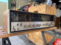
This project was inspired by the now obsolete AirTight M101 Kitset Single Ended KT88 that used Tamura Output transformers , my findings may differ from your take on it or even the parameters I am using , as always safety is paramount with amplifies like this with lethal voltages involved .

https://positive-feedback.com/nos/a...ss impact was very,could have a killer system.

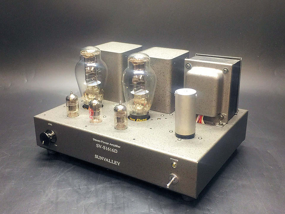
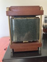
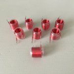
First output transformers tried were the Muse Coils I have, 4.6K , %40 UL or Triode tap or 3.3K /2.25K triode rated at 1.6T @ 25Hz I am very happy with its 2kg mass / chassis footprint 65Wx90Dx120H mm and performance so was good start for this Amplifier , which may develop further.

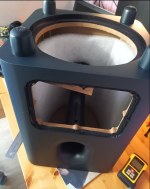
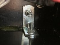
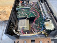
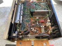
The bog standard chassis from Hammond I used was the Mouser Part Number ,1444-12123 chassis and 2 x 1434-1212 bottom plates used , only problem is the Hammond aluminium chassis are only 1mm thick and had to order two bottom plates , cut one bottom plate in half ,file to size and glue the extra piece under the chassis using a decent glue ie Loctite 480 Instant Adhesive , then 4 x steel brackets bolted in each corner underneath and one each side midway for strength to hold transformer weight , a messy and slow process . Note only the rear half of the chassis was strengthened to 2mm in total for support .

Will likely get a local sheet metal shop to fold a 2mm aluminium chassis and have drop through holes for a hammond 290LX power transformer , tube sockets holes , Tamura output transformer holes and IEC rear punched out in future .

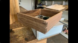
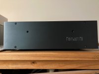
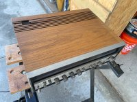
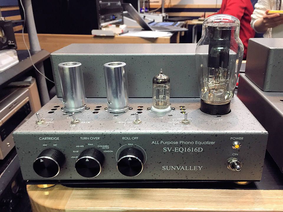
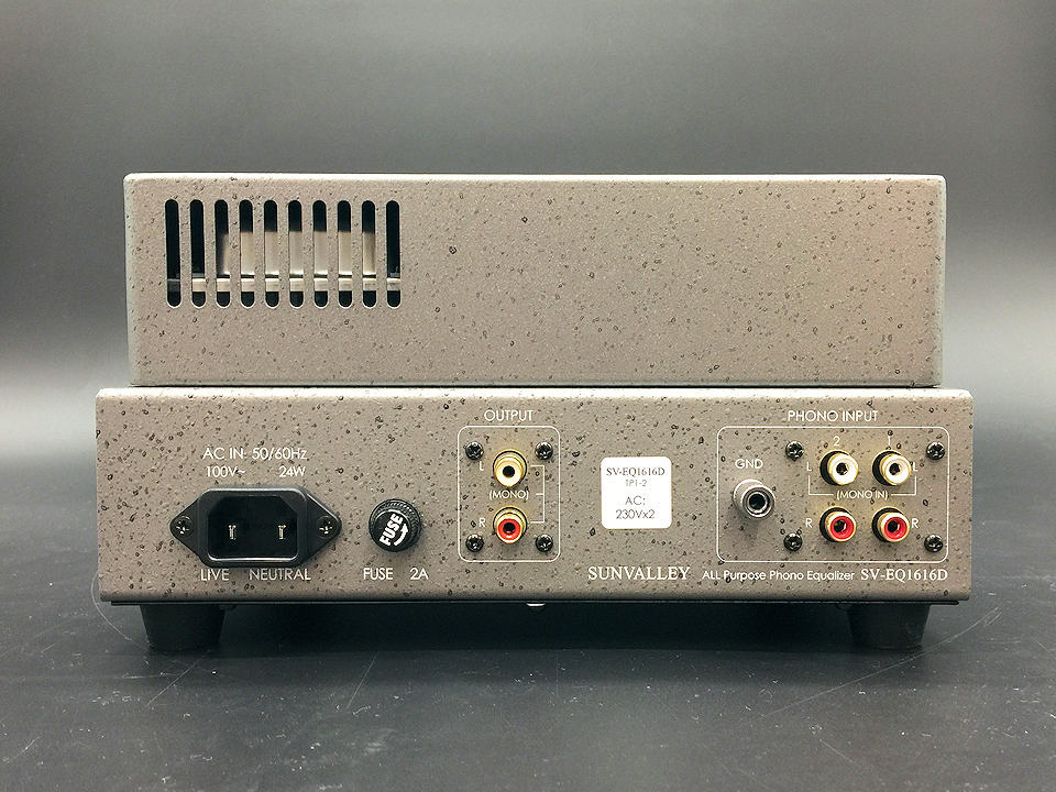
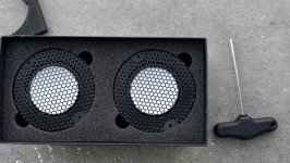
The wooden surround to fit around the Hammond Chassis is Tasmanian Blackwood and Oak for the rear , so stamped speaker / RCA/Power lettering is clearly visible , there is more work to do with further miter cuts to curve corners and flat sections will also be curved inwards .
Once the wooden surround is bolted to the Hammond chassis it will also strengthen the sides considerably .

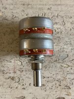
A cutout for the volume control knob at the front will be made for the 100K PEC Carbon Precision series KK/2RV7 potentiometer ,
the best I could find , much more natural sound than plastic film in the signal path IMHO .

https://www.digikey.com.au/en/produ...4m3MbB8DDerkn2rs4tywuTUwLPRRIB-j3JuTna9Tw5iNw

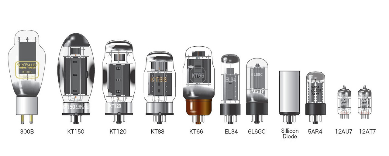
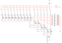
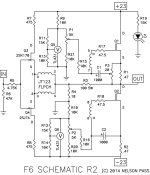
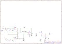
A KT66 will first fitted a tried , drawing below in triode mode , followed by the KT88/6550.
Biasing the KT66 ( B+ 385v ) and KT88/6550 ( B+ 400v ) will take a bit of trial and error as each set of tubes often don't operate near enough to published curves , again a 10 ohm resistor in series with the tubes cathode resistor to get it spot on and output transformers soak up a few more volts than others depending on current required

This project is being shared as a personnel build not a DIY guide as your own designs may well be better .

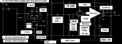
I saw a number of pictures on the net including under the Chassis of the M101 , quite a simple affair of 12AX7 plates strapped together 1.1mA approx and a KT88 biased with a 600ohm cathode resistor 70mA ? starting with the premise of a B+ rail close to 400v DC .

It looked as though the 12AX7 input tube with plates / grids and cathodes strapped together looked to be biased near 1.1mA , mine is now 1.4mA on latest amended version 3 drawing on post below , please ignore drawing on post 5 and bias @ 2mA is incorrect , trouble trying to reverse engineer from old photos , lesson learned always check current with 10 ohm resistor in series . The main dropper from B+ to the 12AX7/12AD7 is 68K !! not 6.8K typo on the KT88/6550 so ignore drawing on post 5 & 8 please .

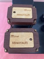
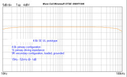
With the latest Muse Coils ( Model MinotauR OTSE - 060NHY-046 ) 1.6T @ 25Hz custom design for me a primary of 4.6K / 3.3K /2.25K / - 4 / 9 and 16 Ohms with %40 Ultra Linear tap for the 4.6K , an ideal set of transformers to use on type 45 , 2A3 KT66, KT88 ( max 8 watts ) and type 50 , 70mA at 4.6K and 80mA at 3.3K / with a %40 UL tap or simply run as Triode !

The Muse Coils are very well made and sound as good as they look , the correct timbre across all types of music is very apparent , excellent frequency extension and solid bass .

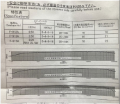
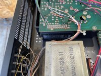
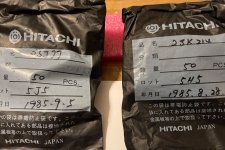
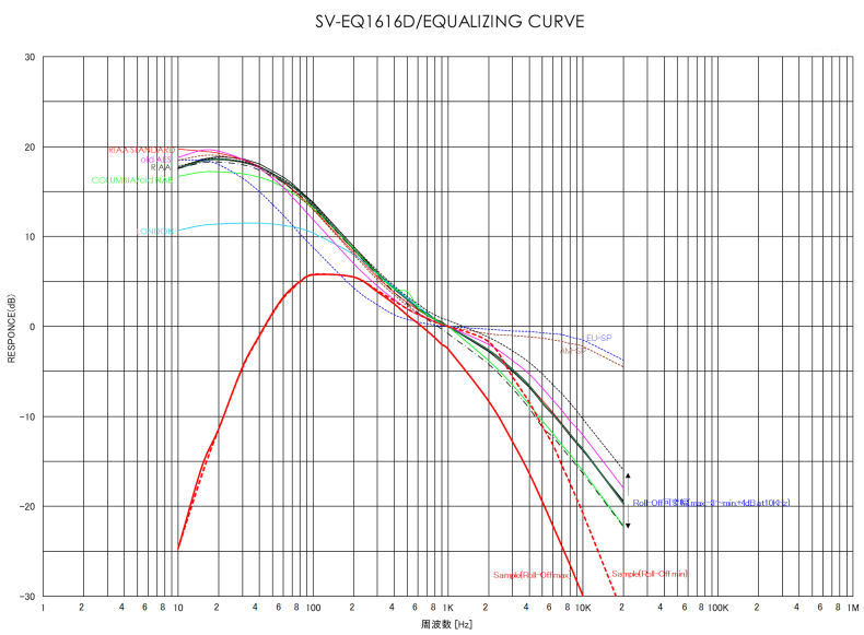
I have a new set of 5K Tamura F915 / 12watts / 70mA / 25Hz -65 kHz with a %40 UL tap output transformers to emulate the " Tamura" sound of the original kitset that I will try next.

I ordered my F915 from SUN AUDIO in Japan , https://www2.big.or.jp/~sunaudio/chumon_e.html they are the agents in Japan and will ship internationally unlike AKIHABARA .

Sun Audio's stock list is a bit out of date but they do have Tamura Single Ended , F912 2.5K F913 3.5K and F915 5K UL in stock , better price than ebay .

The latest Tamura specs and curves are below in my images .


In triode mode the KT66 sound had excellent transparency , full and extended bass and high frequencies , the midrange had all the qualities of a 2A3 but nearly twice the power at 5.8 watts .

The overall impression was excellent with Muse Coils transformer's ( https://musecoils.com/?bot_test=1) , Single HiB cut C / Double Coil.

In Ultra Linear at 7.2 watts the KT66 exhibited more bass slam and high frequency dominance , the midrange was neutral but to match the 2A3 I will remove the Jupiter Copper Foil capacitor and replace with a Toshin DUCT Paper in Oil Vita Q capacitor from the Hifi Collective UK to get more of the AM101 original sound .

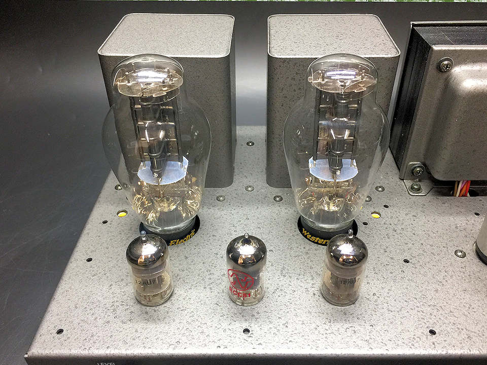
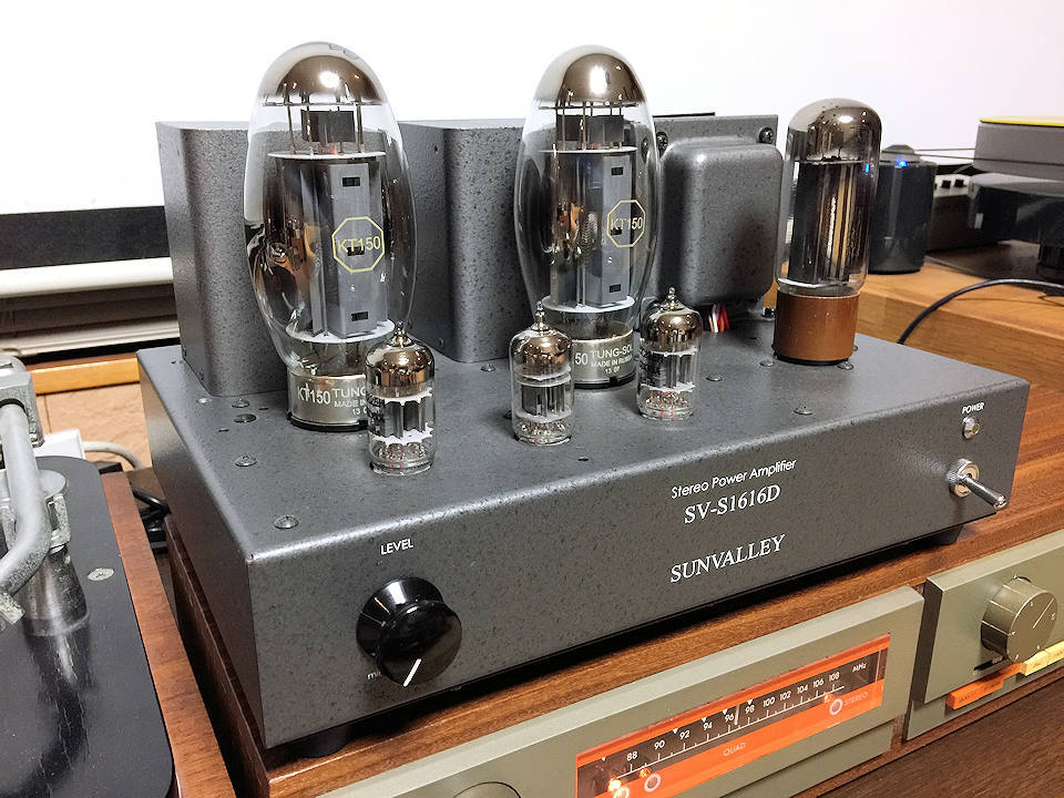
Now I have installed a GE KT88 / 6550 although labelled GE KT88 it looks certainly to be a 6550 which is a highly regarded NOS GE tube .
With 400v B+ my take on the M101 with 12AX7 driver circuit enclosed but remember tube current on the KT88 /6550 can often vary to published curves so always put a 10 ohm 2 watt resistor in series with the cathode resistor to ground and measure volts to ground V = IR you should see 0.7v ( 70mA ) on the lowest setting on your volt meter , somewhat abbreviated . So often the cathode resistor will need too trimmed a little for the desired current .

The 12AD7 I used , same 12AX7 with tighter specs also needed to be trimmed for cathode resistor value , using a 10 ohm resistor to check current .
The sound of the SE6550 in Ultra Linear was very nice indeed , the synergy between the 12AX7 and 6550 produced excellent bass and high frequency extension and the midrange was surprisingly smooth and sweet , I have introduced about 3dB of CFB as this seems the break point where the sound stage closes in a bit , with a Mundorf Silver Supreme capacitor detail was excellent but sound stage pushed forward .
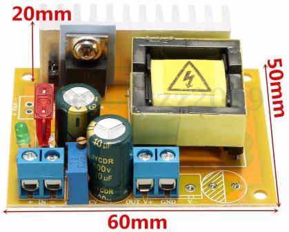
This amplifier has far less distortion than a SE300B at 6-8 watts I have previously built with more dynamics and bass impact , I suspect the SS Hexfreds power supply can attribute a little to this phenomenon
A Toshin DUCT paper VitaQ oil was installed and the soundstage moved further back between my speakers and after more running in will post more findings .

The Problem with the now Vintage AT- M101 kit set is the old carbon resistors and electrolytic's will need swapping out now for longer term reliability , quite a lot of work .

The 12AX7 I decided to use was a NOS Japanese Toshiba 12AD7 the very low noise closely matched version the the 12AX7 with very close matched plates suitable for strapping together .

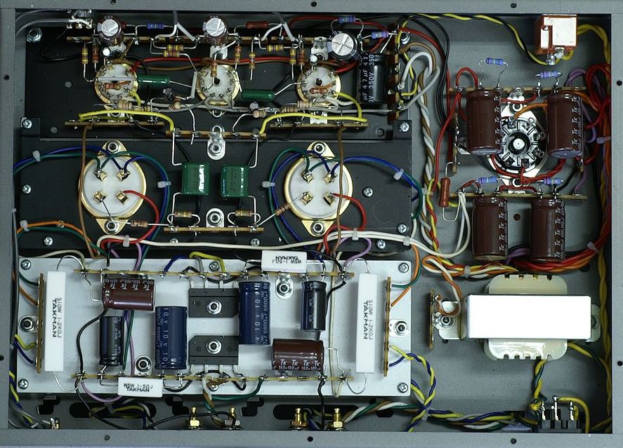
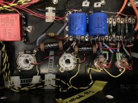
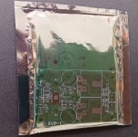
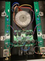
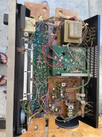
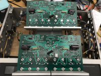
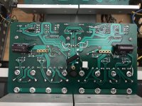
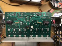
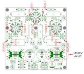
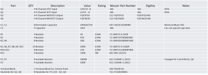
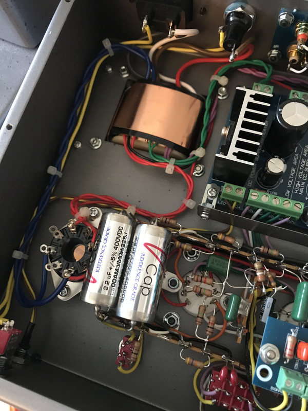
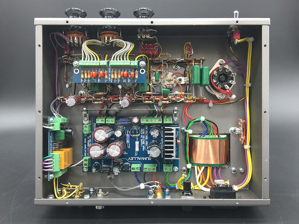
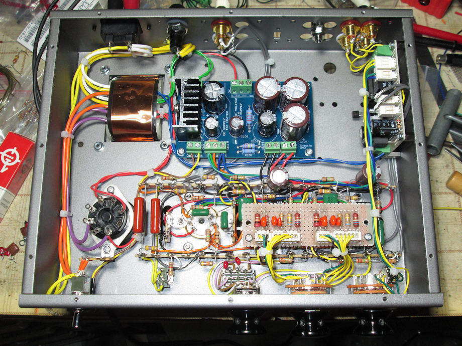
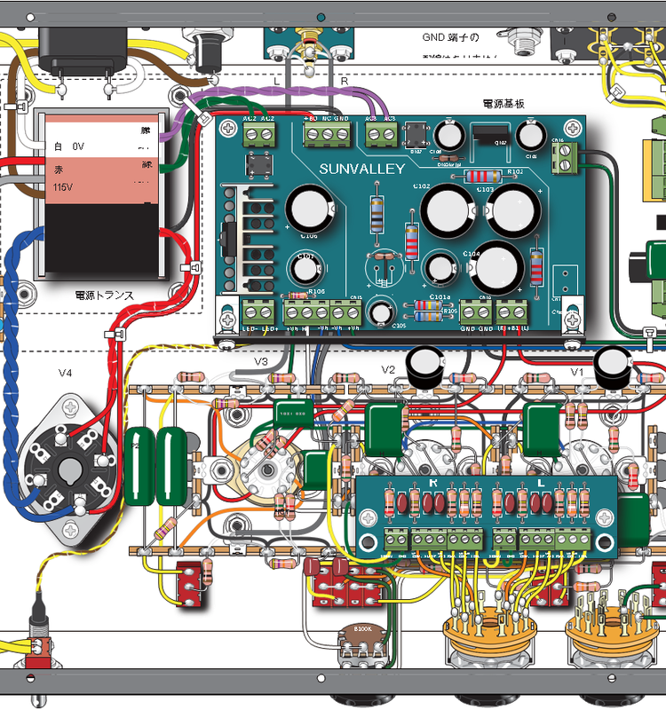
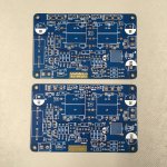
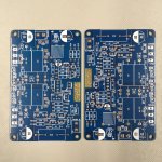
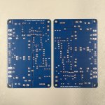
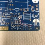
All my signal wiring is point to point copper foil at present and resistors I have chosen are mainly Amtram AMRG & AMRT carbon resistors and capacitors from mainly Vishay Sprague ATOM and a full bridge rectifier using HEXFREDs bypassed with 0.01 uf 1200v ceramic capacitors .

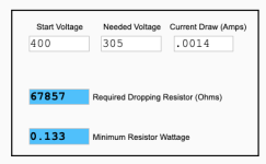
The LM317HV has been replaced with wire wound resistors .

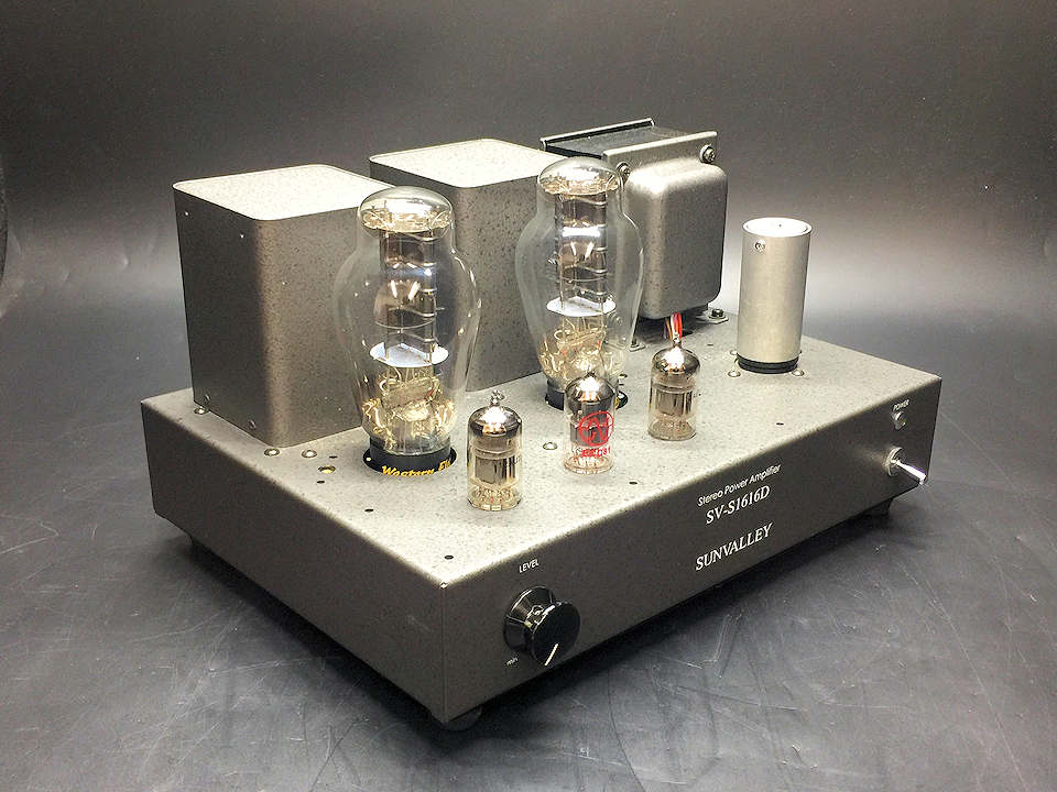
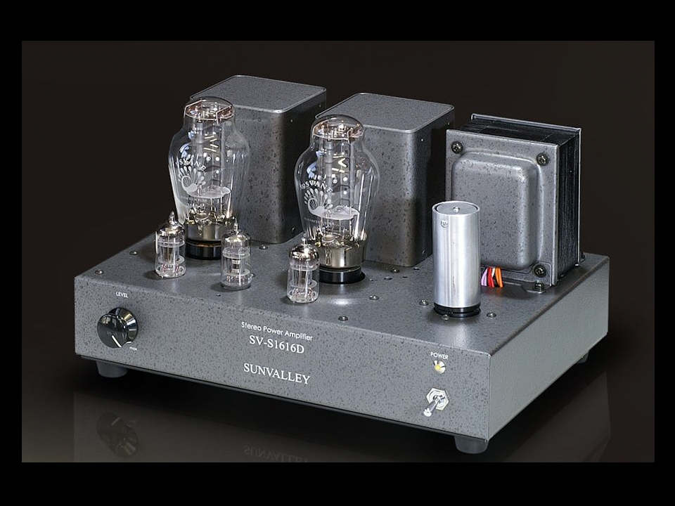
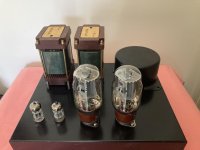
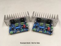
NOW are few pictures of the chassis and woodwork ( almost finished ) to be fitted and Muse Coil Transformer Plots 15Hz - 52Khz -1dB 1K driving impedance.

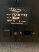
This information is for general interest only and you would need to come up with your own designs for any build and be suitably qualified in what ever country or State you live in to embark on building these projects as inlet power supply involving 110,120,230,240v AC mains voltage and DC voltages in this range can be lethal .ie B+ 400 v

Attachments

  • Muse1.jpg
    Muse1.jpg
    32.6 KB · Views: 135
  • Muse2.jpg
    Muse2.jpg
    35.7 KB · Views: 121
  • Muse3.jpg
    Muse3.jpg
    50.9 KB · Views: 126
  • wood chassis 2.jpg
    wood chassis 2.jpg
    77.5 KB · Views: 115
  • Wood Chassis.jpg
    Wood Chassis.jpg
    85.2 KB · Views: 121
  • Muse Coil Freq Resp.png
    Muse Coil Freq Resp.png
    49.8 KB · Views: 134
  • Under chasiis .jpg
    Under chasiis .jpg
    97.4 KB · Views: 133
  • 400v-305v.png
    400v-305v.png
    15.9 KB · Views: 29
  • 12AX7 .jpg
    12AX7 .jpg
    119.1 KB · Views: 29
  • 12AX7 bias v .jpg
    12AX7 bias v .jpg
    121.3 KB · Views: 41
  • SE K88 UL : 12AX7 version 3.png
    SE K88 UL : 12AX7 version 3.png
    124.2 KB · Views: 43
  • KT66 Triode  mode.png
    KT66 Triode mode.png
    151.5 KB · Views: 19
  • Brackets x 4 .jpg
    Brackets x 4 .jpg
    90.1 KB · Views: 15
  • Tamura 915.png
    Tamura 915.png
    546.8 KB · Views: 9
  • PEC2.jpg
    PEC2.jpg
    99.6 KB · Views: 2
  • PEC.jpg
    PEC.jpg
    127.2 KB · Views: 3

Emotiva XPA-2 Gen1 schematic needed

Hi Guys,
Scored an Emotiva XPA-2 gen 1 power amp today for not much $
Issue is that it tries to turn on but goes straight into protection mode. So like any curious DIYer, off with the lid !
Jeebuz 😳 what a beast !! This thing weighs in at 35kg, has a 1200VA toroid and 12 x 15000/50V electro in the main pwr supply.
Rated at 300wpc these appear to be quite well regarded.
Anyways, I've pulled the DC power supply board but can't find anything that stands out as failed.

This thing has a soft start board that can auto select 120v or 240v and is also tied in with the protection circuit to open the mains relays if a fault is detected.
It is powered by its own 10va transformer.

Anyways, looks like it tries to power on, lights come on and relays click, then after 2 seconds, it shuts down.
This one is going to be tricky !
I've emailed Emotiva service but they have decided not to respond.
Does anyone have schematics for it they can send my way ??

D'Agostino Factory Tour

Here you go:

Login to view embedded media
The aesthetic is definitely not to my taste BTW - I am posting this for academic interest. There are a few aspects shown in the video that I find interesting. One of the comments remarks about the lack of ESD straps, but if you are working in a strictly bipolar world, is that a big deal? (personally, I use a strap even when handling jellybean BJT-based parts, but I am ESD-paranoid). Methinks that the most expensive components shown are the CNC-milled enclosures and level control. The exposed moving coil movements, sitting on egg cartons, are curious.. You can't use compressed air on them, so how do they prevent fluff from getting into the meter? (that would upset me on an amp that cost 6 figures - I'd be expecting Rolex levels of dust hygiene).
  • Like
Reactions: hpavictor

QUAD II mono amp/control unit/tuner (old model-1960)

Hi everyone,

I have an old-model (1960?) Quad II mono-amp with control unit and MW/SW/LW tuner, which was working fine about 20 years ago, including the green cat´s eye tuning monitor. It went into "safe" storage for a number of years, next to the garage, but a rainstorm 2 years ago caused a leak in the roof, with water dripping heavily onto the set. I only discovered that long after it had dried out.

When I tried it out recently, all the valve filaments did light up very nicely, but the set didn´t work. The volume control crackles loudly and amp output is very noisy, even with all possible filters set. Each time, the set only works for a short while until it stops. The tuner only receives one AM station (v. faintly) and the green cat´s eye won´t work either.

Then I tried it out only the amp and the control unit, connecting the earphone plug of an old cassette player to one of the AUX inputs, but output is noisy with very faint signal.

Opening the three modules to look inside, I didn´t really see anything I could understand - I don´t really know what to look for, although I do have all the documentation, manuals and electronics schematics.

I wonder if it will be possible to try and save this set, or if it will be worth the trouble, and would appreciate any possible comments to this respect.

I´ve seen some threads here related to Quad II repair, but I can´t tell if the repair-work done there would apply to my case.

At the moment, I´m trying to get a video and a photo out of my mobile phone to attach to this message as illustration for the previous paragraph.

Cheers for now, and thanks in advance!
Aleatorylamp

Making a Variac more optimal

G'day Guys,

I managed to find a 2KW single phase variac for 100 kiwibucks a wee while back.
https://www.aliexpress.com/item/100...OCdnqQdW&utparam-url=scene:search|query_from:

One of these but without the fuse holder which is problem #1
Problem #2 is the analog meter is pretty poopy. At 230Vac output according to my DMM the analog meter reads 220Vac.
Problem #3 is the connections. Having to wire things in ever time will be a pain in the buttocks.

So my evil plan is to graft a large plastic jiffy box on the front so that I can mount the extra bits to make it more usefull:

Here's the block diagram.
Block diagram.png

So far I have tested the variac to make sure it works as intended: check.
I checked the accuracy on the built in analog meter as per above. 10Vac out at 230Vac
I also checked the function of the digital meter: much better. 2Vac out at 230Vac

Next up is to start cutting into the jiffy box to mount the goodies.
After that I will need to figure out how to mount the jiffy box to the front of the Variac chassis. Probably rivet nuts.
  • Like
Reactions: Mainframe

  • Locked
For Sale PCM63P-K chips + DAC board + IV board

**Sales is now withdrawn.
I would use the chips.**

A good buddy of mine here has decided not to proceed with his PCM63P-K project, hence selling the following package:
1. A pair of brand new unused PCM63P-K chips
2. Miro PCM63 board ( no parts installed, as pictured )
Information can be found here : PCM63 board
3. Pedja Rogic OPA861 I/V stage. Board with all parts soldered on but have not been tested yet. You will need to power it up, test, debug (if required)
Information available here : https://www.audialonline.com/blog/opa861-zero-feedback-output-stage-of-aya-ii/

All these for US$195 or preferably Singdollars 252, shipped.
Paypal FF only please.

For Sale 12x TPA3116/8 PBTL bare pcb + IC soldered from Dug's GB

Hello, I have 12x PBTL amplifier boards for sale with TPA3116/8 IC soldered and tested. These are from Dug's GB a while ago. I will include 2x 10uH inductors with each PCB (Sumida CDEP147NP-100MC-125).

The boards are packed already 4 pcs. each, so I would like to keep them that way and would sell 4 boards (incl. 8 inductors) for 45 EUROs plus shipping from Germany.

These have been out of another never finished project.

Please let me know if you have any questions.

Best regards,
Klaus

Attachments

  • 20250430_151053.jpg
    20250430_151053.jpg
    463.7 KB · Views: 60
  • 20250430_151223.jpg
    20250430_151223.jpg
    277.6 KB · Views: 54

JFET-only Circlotrons without negative feedback

There is a desire to make a powerful amplifier exclusively on JFET.
Without negative feedback.
Tested circuit at low power is already available.
There is now a powerful MOSFET output scheme.
The next step - a powerful circuit Si-C JFET.

Related topic:
JFET-only Headphone Amp "Circlotron КП903B".

Attachments

  • Цирклотрон_ КП1_303&#104.jpg
    Цирклотрон_ КП1_303&#104.jpg
    127.4 KB · Views: 4,718

For Sale FirstWatt F6 original prototype

Offered here, for your consideration, an original prototype FirstWatt F6. Built and sold at auction in support of Burning Amp by Papa in 2023.

This amp is of the original design configuration that used SemiSouth JFETs, not the MOSFETs that the commercial F6 used. Note the dual LEDs on the front. I have no proof but I believe Papa assembled this himself. The amp was opened and pictures taken at BA that year, I have not opened it nor messed with it or put it on any test gear, but I have listened to it lots in my main system. There is nothing at all wrong with this amp. To my ears, and in my system, it is the most detailed amp I have heard, but for some mysterious reason I favor the air and liveliness of my F5m and Aleph Jzm more.

I paid $2600. I am asking $2600, plus shipping to your locale (it will come in the factory original shipping box). If you happen to reside in Northern California, I'm open to arranging a pickup but please be patient with me as I work for a living and have some travel coming up. This isn't about the money, it's not a forced sale, I'm not in a hurry, no low ballers, I know what I've got, etc., etc. I've just listened to this amp enough to learn from it and I'm willing to pass (haha! Pass) it on to another aficionado.

Thanks for looking.

Attachments

  • F6_SCH_R2.jpg
    F6_SCH_R2.jpg
    239.6 KB · Views: 353
  • IMG_9258.jpg
    IMG_9258.jpg
    649.7 KB · Views: 351
  • IMG_1291.jpg
    IMG_1291.jpg
    490.7 KB · Views: 316
  • IMG_1292.jpg
    IMG_1292.jpg
    312 KB · Views: 303

Vintage Receiver score - Sony STR-6036A

Woot, I just scored an old receiver! It's a Sony STR-6036A. Not for the main system, but the vintage look is kinda cool for somewhere else in the house. My wife spotted it on FB buy-nothing group locally, what an enabler!

Here are some pics, attached.

I'm in the process of doing simple external cleanup. I'm going to have to fix the broken slats on the vent on top. I bought some oak 1/4 in. by 1 to cut down to the right size, and tried to choose a stain that looked like the right color. Info I could find online called the finish 'light walnut' but Home Depot only had much darker walnut. I hope I can match the finish, but fear I won't be able to.

Knobs and switches are all dirty. I saw some guy spraying Deoxit in them on youtube and figure I'll do the same. But I do have this question: one source said don't use anything that leaves a residue to clean the tuning capacitor (use what, then?), another guy said use Deoxit, just spray it out with compressed air afterword. What does the vintage restoration brain trust say? I have Deoxit and an air compressor, that part's NP.

Otherwise, it seems to work. I played a bit of FM through it, but haven't done more than that, I'll have to finish going through it. This is ~ 1972 vintage, so part of me says all the electrolytics should be replaced. Another part of me says that if it ain't busted, don't risk making it busted. I'm mostly here for the speakers, I know a bit about the electronics but I'm probably not going too deep into the guts here.

Chime in if you have experience with one of these units, or know what I should be doing with mine!

Attachments

  • IMG_4106.jpg
    IMG_4106.jpg
    453.3 KB · Views: 35
  • IMG_4107.jpg
    IMG_4107.jpg
    595.1 KB · Views: 31
  • IMG_4108.jpg
    IMG_4108.jpg
    543.7 KB · Views: 30
  • IMG_4109.jpg
    IMG_4109.jpg
    723.1 KB · Views: 32
  • IMG_4110.jpg
    IMG_4110.jpg
    639 KB · Views: 30
  • IMG_4111.jpg
    IMG_4111.jpg
    588.5 KB · Views: 30
  • IMG_4112.jpg
    IMG_4112.jpg
    647.2 KB · Views: 29
  • IMG_4113.jpg
    IMG_4113.jpg
    528.5 KB · Views: 33

Fourier Transform Speaker

I don't know if this guy's speaker will ever be marketable but he's got a playing prototype, and I've not seen anything like it before.

If I'm understanding the concept correctly; a typical digital audio setup recreates a music signal as a mixture of pure sine waves that mix and interact via the Fourier transform principle, and the mixing occurs within a digital processor, upstream of the power amp(s) and speakers.

In contrast; in this guy's setup the mixing of the component sine waves occurs at the speaker itself. That is; driving each speaker are twenty separate signal processors feeding pure component sine waves into twenty amp channels-- discretely driving twenty drivers in each speaker. As such, the Fourier transform occurs at the speaker itself, as the separate driver outputs blend together in front of the speaker.

That's a lot of digital processors and amp channels so even if this guy succeeds in taming all the gremlins, it's a complicated and expensive setup.

Enjoy!

Login to view embedded media

Thermal measurements for Modushop Galaxy 1GX388 2U chassis

I am planning to use a Modushop Galaxy 1GX388 2U 330 mm by 280 mm by 80 mm chassis for a pair of Zenductor 2 amplifiers. To find out whether the 10 mm thick corrugated sidewall profiles are sufficient as heatsinks for 15 W to 25 W dissipated power per side, I did thermal measurements with a DC power supply, a 100 W 8 Ohm power resistor, and a thermal camera built into my cell phone.
The answer is that the chassis should work as is, i.e. without replacing the side walls with real heatsinks.

I attached the power resistor with a pair of spare M3 screws and nuts (supplied with the chassis) to the center region of the flat middle section of the 2-channel side of the Galaxy sidewall profile, and ran tests at about 18 W and 39 W, both with the wall free standing and as part of the assembled chassis (with the rear panel partially slid in, to leave an opening for the resistor power cables, and the remaining opening mostly blocked against air movement).
Temperatures stabilized after 20-30 minutes, and were lower than expected. From the measured temperature rises, and correcting for the heat loss directly from the resistor body to ambient, I compute a thermal resistance of about 1.4 K/W or °C/W.

Graph of four measurements (two power levels, freestanding and chassis-integrated heatsink):
Galaxy Heatsink Temperature.png


Ambient temperature (the zero level of the graph above) was about 22°C. Interestingly, the equilibrium temperatures for the heatsink (corrugated 10 mm sidewall) were lower in the chassis than free standing. The increase in effective convection surface, from bolting on the other four panels of the chassis) must outweigh the shielding effect of the case.
Between the second and third measurement series, I installed (slid, with the screws and nuts already in place) the sidewall into the chassis.

Also interesting (to me) is that radiation losses are not negligible. A sidewall (448 cm^2, counting both surfaces, but not the corrugations) at 40°C radiates about 5 W more power into a 22°C room than it absorbs. I chose NOT to correct for radiation, since the effect will be of similar magnitude in the real application of the chassis.
As mentioned, I did correct for the direct convective losses from the power resistor, by measuring the resistor equilibrium temperature of 120 °C (!) at 9.68 W, with convection shielded from the resistor mounting surface (sitting on an insulating surface), giving a thermal resistance of 10.2 K/W.

The thermal resistance from the resistor case to the heatsink computed as about 0.5 K/W, which should be similar to achievable case-to-heatsink resistances for transistors. No thermal compound was used.

Example of a thermal image (equilibrium image for 18 W power, resistor mounted to side wall inside the chassis):
flir_20250428T214452 - Copy.jpg


The resistor mounting position 'shines through' to the outside surface; I used the maximum, center temperature as heatsink temperature for my calculations. This choice should give correct results for the estimated case temperature of the device to be cooled. The average heatsink (side wall) temperature will be lower than computed from the effective thermal resistance of 1.4 K/W.

Resistor mounting position:
IMG_20250428_225215 - Copy.jpg
  • Like
Reactions: Dave Zan

AB100 Class AB Power Amplifier

AB100 Amplifier - Micro Article by Nelson Pass

Since villagers armed with pitchforks and torches have begun camping
out my front door demanding a Class AB power amplifier, and

Whereas, I am inclined to demonstrate my goodwill in this manner and
do in fact have a 13 year old piece laying around unpublished,

I Hereby Present the AB100 Class AB Bipolar power amplifier.

Salient Specifications:

Rails: +/-50V or so

Gain: 36 dB (this was the request of the people who commissioned
this but did not want to pay for it)

Bandwidth: 5 Hz to 100 KHz (-3 dB)

Damping Factor: about 500

Maximum power: 100 Watts 8 ohms, 200 Watts 4 ohms

Slew Rate: 30 V/uS

Bias Current: about 0.08 A per channel

Following are several graphics. (Unfortunately I scanned them in the
distant past, so the quality is not up to my usual standards)

Let It Not Be Said: That I never did anything for you....

😎

Attachments

  • AB100 001.gif
    AB100 001.gif
    101 KB · Views: 23,415
  • AB100 THD 8.gif
    AB100 THD 8.gif
    58.7 KB · Views: 21,214
  • AB100 THD 4.gif
    AB100 THD 4.gif
    59 KB · Views: 16,544
  • AB100 THD FREQ.gif
    AB100 THD FREQ.gif
    58.5 KB · Views: 20,007

Hello DIY Audio

I've been messing with audio and electronics since I was a teen. Made more than my share of smoke. But some successes too. I have most of my luck with turntables and tape decks. But I did once get a Dynaco ST120 working on my own. Took two tries, though. I learned to ask why that transistor failed before just replacing it. I am digging out some of my old audio gear and checking it out. I figured having this forum as a resource would be helpful. I've visited occasionally over the past couple of years and I find the content very interesting. Even when it goes over my head.

Chassis Discussion

This thread is for discussions about any of the chassis. For more information on this product, please see the product page below.


Threads on diyAudio or elsewhere on the internet that show off what can be done with these chassis or give creative ideas:

Low Rp tube for line stage - ideas?

What would be a good sounding low Rp triode for a line stage? Requirements - Rp under 2K and low gain, like under mu=10.

Possibilities include:
7233 - 230 ohms
A2293 - 380 ohms
6S19 - 420 ohms
12B4 - 1K
6CK4 - 1.2K
6AH4 - 1.8K

6BX7 - 1.3K (double triode)

4P1L - 1.5K (in triode) DHT (needs 25mA or more)
71A - 1.7K DHT (getting rarer and more expensive)

There are also all the 6AS7/6080 type tubes and bigger DHTs like 2a3/6B4G/6C4C but that would be overkill.

2SC3503E & KSA1381ESTU Group Buy

Onsemi announced that KSA1381ESTU is end of life with a last order date of Jan 5, 2025. Is there any interest in a group buy for these?

My thought is to combine it with a group buy of 2SC3503E which is available from Rochester Electronics (link here), but only in large quantities (1000+). This makes for a good pairing as KSC3503 is currently only available in D grade.

Lot sizes will be 100 pieces of each device.

As this would be a large cash outlay for the initial purchase, we'd probably need to have money up front. We'd have to backorder them as both Mouser and Digikey are currently out of stock, but accepting backorders. Maybe it'll arrive in time for Christmas.

I will keep the first post updated with anyone interested in participating.

PRICING UPDATE:

Pricing factors in the price to order, taxes, shipping and repacking materials with a bit of a bump so I don't hopefully loose money on this.

Round 1: $30/100. For example, 100 x 2SC3503E and 100 x KSA1381E would be $60 + shipping.

Round 2: $30/100 for 2SC3503E and $35/100 for KSA1381E. The higher price in round 2 for KSA1381E is due to a price hike on Mouser's end.

SHIPPING:
For shipping, US will be $5. International will be $20 if the quantity is 100/100. If over this, I'll PM an estimate. This is due to the weight threshold where international shipping prices increase.

VAT: If there is VAT in your country, I understand this will be collected from the recipient, not paid by me.

TIMING UPDATE:
The Mouser order for KSA1381ESTU has been placed. Its backordered at Mouser with a restock date of 11/11/2024 (if Mousers date is accurate).
Domestic orders arrive in the second half of November.
International orders will go out via USPS international which shows shipping times of 1 to 4 weeks.

PAYMENT:
I'll send payment info once I get close to being able to ship. I have PayPal and Venmo.

April 2025 UPDATE:
The Mouser order for KSA1381E failed to come through. Mouser canceled the order despite it being placed months ahead of the final order deadline. It's unclear if this is a Mouser or OnSemi issue. We looked extensively for alternate sources of KSA1381E but could not locate anything that was cost effective. It was determined that KEC KTA1381Y was the next best alternative.

April 20, 2025: Profusion order for KEC KTA1381Y placed.
April 25, 2025: Profusion order received
April 30, 2025: Estimated Ship Date for Round 1 order (for those that have paid)
Early May: Payment instructions to be sent for Round 2 participants


ROUND 1: Closed for new participants (Shipping April 30 ,2025)

RegionUser
Status​
2SC3503E
KTA1381Y
North America@ticknpop
SHIPPED
100​
100​
North America@uptownsquash
Local Pickup​
200​
200​
North America@Kokanee
SHIPPED
100​
100​
North America@OZAM
SHIPPED
200​
0​
North America@kannan_s
SHIPPED
100​
100​
North America@manniraj
SHIPPED
100​
100​
North America@saabracer23
SHIPPED
250​
0​
EU / UK@HRDSTL
SHIPPED
800​
100​
EU / UK@Peterspx
Combine with @HRDSTL
100​
100​
EU / UK@Flikoman
SHIPPED
100​
100​
EU / UK@Kovax
SHIPPED
100​
100​
EU / UK@mahtew
Payment Request Sent​
400​
100​
EU / UK@StevenCrook
SHIPPED
100​
100​
EU / UK@chermann
SHIPPED
300​
0​
EU / UK@Chrisr3521
SHIPPED
100​
0​
Oceania@Dave Zan
Payment Request Sent​
100
100
Total
-​
-​
3150
1300


ROUND 2: Closed for new participants (Shipping early May 2025)

RegionUser
Status​
2SC3503E​
KTA1381Y
North America@icsaki
SHIPPED
300​
300​
North America@rss388
Payment Request Sent​
100​
100​
North America@Michael327
Payment Request Sent​
100​
100​
North America@bloqhed
SHIPPED
100​
100​
North America@yoaudio
SHIPPED
100​
100​
North America@CritterSoft
SHIPPED
300​
300​
EU/UK@KimH
SHIPPED
100​
100​
EU/UK@Captain B
Payment Request Sent​
100​
-​
EU/UK@Edgar
Payment Request Sent​
100​
100​
Total
-
-​
1300
1200


ROUND 3: Open for new participants (based on available stock)

RegionUser
Status​
2SC3503E​
KTA1381Y​
North America@asuslover
SHIPPED
-​
100​
-Available
Available​
1400​
-​
Total​
-​
-​
1400​
100​

Hello diyAudio members from an audio enthusiast in Ohio, USA

Hello,

I am a collector of audio equipment from the 70s through 90's, with an emphasis on the 80s. I've been actively collecting for about 5 yrs, gathering all the bits and pieces I wasn't allowed to touch or couldn't afford when I was younger. I have a particular interest in the odd and rare.

This forum has been a goto for me. Thanks for all the help. Hopefully, I'll be able to contribute in the future.

MnM

NAD C390DD (C 390DD) does not power on failure with fix

I was repairing a NAD C390DD for my friend and tough I'll post the solution here too as this type of problem is likely to happen on other units and I did not find it documented in web prior to this.

Symptoms before fix

A) When powering on from back panel power button the orange 'sleep LED' comes on
B) After push of the on/standby button on front panel 1 click of a relay can be heard and the orange led turns blue ... display will so no sign of life. Not other relay clicks follow. The unit does not switch on.

Problem appeared to be in secondary PSU which supplies the +5V and after switch on the +12.5V.

The +12.5V power line showed only +4.5V after the step B. So clearly something wrong. Anyhow, longish troubleshooting later it turned out to be a fault in following capacitors.

Hope this helps someone in future.

Attachments

  • PSU_block.jpg
    PSU_block.jpg
    33.8 KB · Views: 1,470
  • c390dD_sch.png
    c390dD_sch.png
    155.9 KB · Views: 1,528
  • c390dD_Psu.png
    c390dD_Psu.png
    128.8 KB · Views: 1,472

For Sale Antek transformers

I have used Antek transformers for sale. Revised price and shipping cost

AS-4220 opens box but never wired up. Asking $40.00 plus actual shipping cost to lower 48 states. SOLD
IMG_2321.jpeg


AS-4432 limited use once then removed. Asking $40.00 plus actual shipping cost to lower 48 states.
IMG_2323.jpeg


AN-5220 used, asking $45.00 plus plus actual shipping cost to 48 lower states
IMG_2324.jpeg


AS-3218 used pull from dual mono amp. Asking $30 each plus actual shipping cost to lower 48 states. Sold
IMG_2326.jpeg
  • Like
Reactions: birdbox

Vanguard Scout Speaker

I have developed a new 5.25in 2 way bookshelf speaker to go with the Vera-Link TWS Bluetooth amp. It’s a vented 2 way bass reflex design superbly finished in rosewood veneer and equipped with a custom voiced crossover using quality components (film caps and heavy inductors, and premium wire wound resistors). The woofer is a treated paper cone with a large motor and the tweeter is a 25mm soft dome with low distortion and a smooth silky response. The voicing is similar to my other speakers but the crossover is lower at 1500kHz and asymmetric filter slopes with all positive phase for realistic transients. I would say that the speakers have a punchy bass and a delightfully fun and musical sound signature. I have put several of my playlists through them and it all sounds great.

Speaker Dimensions: 17cm W x 24cm D x 30cm H

This was early crossover development with P2P Wago connectors:
1696940063282.jpeg


I’m going with the all film cap crossover on the right. The one with the bipolar cap on left was just a sample for grins.
1696939863083.jpeg


1696939793873.jpeg


Here is the assembled speaker with the Vera-Link amps installed:
1696939945234.jpeg


Setup in my bedroom (amp on dresser not being used):
1696939985631.jpeg


The Vanguard Scout is a super sounding and beautiful looking speaker and will be offered at only $299 a pair. But if you buy it with the Vera-Link TWS Bluetooth amps together, the introductory bundle price is only $449.

Summary of Vanguard Scout:

The Vanguard Scout is a compact 2 way bass reflex speaker with a 5.25in treated paper cone woofer and a 25mm silk dome tweeter in superbly crafted rosewood veneer cabinet with a satin finish. What makes the Scout special is the crossover and how it is voiced to provide a smooth presentation with pinpoint imaging and a wide soundstage. The crossover uses high quality custom inductors and film capacitors typically seen on speakers costing 10x the price.

The crossover is a unique asymmetric topology that produces crisp and accurate percussion. The bass extension is deep for its size with a 60Hz -6dB point. The silk dome tweeter provides resolving highs while maintaining a smooth sound that is low in distortion. The treated paper cone woofer has a natural and lively sound with a slightly warm midrange that’s perfect for vocals. The balance and voicing of the Vanguard Scout is optimized for non fatiguing listening pleasure with all genres of music.

This speaker is the perfect introduction into great sound. Paired with the VeraLink TWS Bluetooth amplifier, it provides a complete music system - simply add your smartphone or other streaming decide with Bluetooth connectivity such as an Amazon Dot (Alexa) which enables multi-room playback capability.

Need help understanding bode plot phase shift

Hey guys! I have been trying to design my own simple small signal circuits for using in my condenser microphone. I am pretty new to this, but I was able to get some designs that perform well in regards to THD and Bandwidth. However, when I perform an AC analysis, the bode plot that is displayed also shows the phase relationship within a range of frequencies. When I do a search to understand how much phase shift (or what kind of phase shift) I should see, I can't find an answer. There are tons of videos and blogs that show how to measure the phase shift, but none really saying "how much" I should allow in my design. I saw one guy on reddit saying he allows no more than 10 degree shift from zero. So how much phase shift should be allowed in a well designed circuit? Also, will I be able to hear this as long as the shift is distributed evenly throughout the whole "audible" frequency range? I will post some pics of my bode plot from qspice, and maybe somebody can give some feedback on it.

Here is one where the shift seems to be even up to around 25Khz
Bode-Plot.png


Question 1 - is this amount of phase shift considered acceptable in (hifi standards)? Or at least professional standards?
Question 2 - is this going to be audible?

Here is another plot with a more complicated situation going on (180 degrees)

bode plot 2.png


This one has some corner frequencies from some inconvienient bypass caps I had to use.

Question - this shift in the low frequencies, is it normal? Will this cause the low end to be cancelled out or distorted?

Thats it, thanks for reading, any feedback would be really helpful.

Spectral DMA 100 Help needed

Hi,I have a stripped Spectral DMA 100 amplifier,need help finding power supply specs for both driver and output.
I have a need to build power supplies as the chassis is missing both transformers……maybe use the chassis,I do have a Diyaudio 5U chassis new in the packing…I have been saving it for a new project,or,if the transformers needed can fit the original chassis,maybe use the Spectral case.
all outputs verified ok.
The boards appear to be prototypes,there is no serial number sticker on the back of the case….found at the Alameda Antique Fair,SanFrancisco in 2017…..
thanks,Dave Grady

Attachments

  • IMG_0859.jpeg
    IMG_0859.jpeg
    391.6 KB · Views: 372
  • IMG_0858.jpeg
    IMG_0858.jpeg
    526.3 KB · Views: 418
  • IMG_0860.jpeg
    IMG_0860.jpeg
    469.1 KB · Views: 379
  • IMG_0861.jpeg
    IMG_0861.jpeg
    448.1 KB · Views: 359
  • IMG_0862.jpeg
    IMG_0862.jpeg
    532 KB · Views: 320
  • IMG_0863.jpeg
    IMG_0863.jpeg
    502.5 KB · Views: 334
  • IMG_0864.jpeg
    IMG_0864.jpeg
    449.3 KB · Views: 327

For Sale 2SJ77 / 2SK214 Hitachi TO-220 MOSFETs

I have a rather large quantity of these extremely versatile MOSFETs. They are of -85 vintage.

Can be sold in pairs or as sealed bags of 50.

Rated at 160V they can in many instances be used instead of 2SJ79/2SK216.

Perfect as drivers in power amps.

$20/pair. Shipping at cost.

Regards
RM

Attachments

  • IMG_1649.jpeg
    IMG_1649.jpeg
    772.6 KB · Views: 158
  • IMG_1650.jpeg
    IMG_1650.jpeg
    659.4 KB · Views: 126
  • IMG_1651.jpeg
    IMG_1651.jpeg
    511.6 KB · Views: 121
  • IMG_1652.jpeg
    IMG_1652.jpeg
    756.3 KB · Views: 129

Class D Amp Photo Gallery

There are plenty of cool pictures in the photo gallery threads posted in the other forums, so it only seems right that there be such a place to post your amp photos in the class d forum as well.

It doesn't matter whether you've got a prototype working on the breadboard, an amp jerry rigged on the table, or an electronic masterpiece in a case; post your stuff here for everyone to check out. It's a good way to share ideas and may even give someone a little bit of inspiration to tackle that project they've been wanting to do 🙂
  • Like
Reactions: Jcris

Building BA-3 as analog output stage of noDac

Hi guys, as tittle said "Building BA-3 as analog output stage of noDac", well the noDac outputs 0,19Vrms so I was looking for something with a gain x10 to get near the standard 2Vrms, helping me to take the BA-3 option because I own original SK170BL, SJ74BL, K2013 & J313 from when I used Erno Borbely stuff, also it's not complicated to do it and adjust (very similar to Borbely), don't take to much room inside noDac box and is a lot of more easy and a lot of less money than make a DHT 4P1L with the same gain of course I don't expect the same SQ.

I read with attention NP BA-3 article, it seems with standard resistors values BA-3 fits nicely the x10 gain I'm looking for.

Attached NP BA-3 article to know if it's the latest or there is other new and also B.O.M. for a balanced unit that I will not do because all my system is SE.

I read Jfets have to be "matched if possible" at 10mA Idss, I have on hand:

SK170BL
9.48mA x 2

SJ74BL
9.02mA x 1
9.03mA x 1
or
10.11mA x 1
10.24mA x 1
What's best pair to use with the SK170BL?

I guess with these values P1 & P2 will remain 500R, right?

With the input voltage of +-25V can reach the x10 gain?

I will post pics of my work in progress.

TIA
Felipe

N.B. Big thanks to Jim aka 6L6 to give me a couple of PCB.

Attachments

  • BA-3 B.O.M..png
    BA-3 B.O.M..png
    257.4 KB · Views: 44
  • BA-3.pdf
    BA-3.pdf
    927.4 KB · Views: 66
  • Like
Reactions: 6L6

Hello, from Athabasca, Canada

I'm currently getting into voiceover recordings for Librivox, and looking forward to polishing down down some over-produced demos (davenoel.bandcamp.com). I'm currently building a collection of cheap mic bodies and ordering new capsules and preamp boards to swap in. I wish the BM800s out of china weren't so varied in builds, at least they use the same case for easy pcb replacement.

Spending time obsessing over schematics is a great way to avoid actual work!

I'm also building a mastering quick speaker preview array with mono sum and difference switches and various car and home speaker sets built into a large speaker array. The idea is if it can sound not as bad as anything else on various shitty 6x9's and 2" computer speakers, hopefully it will sound good elsewhere.

How to build a S/PDIF coax input selector

Hey everyone
I've got a few digital sources hooked up to my system and I'm frequently comparing DACs. I'm looking for a better way to switch between them. Right now, I'm using a cheap external switch box, but it's not ideal and adds another cable going to the DAC.

What I'd really like is a professionally made switch built right into my DAC's case, so I don't need any extra cables. What's the best approach for switching coaxial and S/PDIF inputs?

I'm thinking a basic rotary switch probably isn't the right way to go, am I right?

YH11068A 10-32V to 45-390V dc/dc - guess the control ICs

You may have seen this neat dc/dc available recently, especially given the wide variable B+ setting capability, and quite high power rating, and ability to run off 12VDC.

PS5a.jpg


For low power valve amps (eg. up to 6V6 push-pull) they should make it very convenient to power just from a 12VDC 4-5A plug-pack.

The initial intrigue is what control IC's are used, as the 8-pin packages are defaced.

To help the guessing game, the attached doc has my first pass at a schematic drawing. No doubt I've misinterpreted a few parts, and the IC pin numbers are based on what I think are the pin 1 dimples that haven't been defaced completely.

Some strong power saving pulse skipping is going on, which appears as low frequency ripple at times, and at other times it is just pulse skipping at 70kHz ripple. The FET drain waveform is pretty clean and fast, given the simple pcb and parts. The current sense filter cap ground and IC ground seem a compromise of layout. The turn-on appears to be trying to occur close to a zero-voltage dip. No load loss is pretty good.

http://dalmura.com.au/projects/YH11068A.pdf

Ciao, Tim

Warp-1 Amp

The LSA Warp-1 amp based on my TPA3255 reference design amp has been getting some good reviews. I think it is time for it to have a dedicated thread.

The reviews so far include:

ttp://v2.stereotimes.com/post/lsa-warp-1-power-stereo-amplifier-by-greg-voth/

https://www.tonepublications.com/review/review-the-lsa-warp-1-power-amplifier/

https://www.superbestaudiofriends.o...warp-one-class-d-power-amp-impressions.11451/

We also have reviews from SBAF loaner tour here:

https://www.superbestaudiofriends.o...warp-one-class-d-power-amp-impressions.11451/
A new review on YouTube by Thomas and Stereo just came out:

Login to view embedded media

EQ1616D Phono Amp

Stereophile Class A recommended components..

Class A
Best attainable sound for a component of its kind, almost without practical considerations; "the least musical compromise."


Recommended Components 2021 Edition Phono Preamplifiers | Stereophile.com

EQ1616D were nearly old out. The next production will be in July 2021. --> April Production was SOLD OUT.
The Next Production is July 2021.
If you want to reserve a unit of EQ1616D, please let me know.
Thank you for your support!!

Price $985.00 Kit
Assembled Version $1,645 with 2 VCAP ODAM 2.2 (assembled by Sunvalley Japan)


Stereophile Review - November 2020 edition
Gramophone Dreams #42: Sunvalley Audio SV-EQ1616D phono equalizer | Stereophile.com

Sunvalley SV- -EQ1616D 115/230V version (Point to Point Phono amp Kit)
Made in Japan

Price $985 KIT Version
Price $2,050 ASSEMBLED Version ( Assembled by SunValley Japan with tube set (Gold Lion ECC83/B759 X 2 + Brimar ECC82 X 1 + LINLAI/COSSOR WE 274B) + VCAP ODAM 2.2 X 2 (output Cap)
Price $1,585 (assembled version w/o tube set . VCAP ODAM 2.2 X 2 included) + shipping
Assembled Version

This kit does not come with tube set. The following 3 combinations are recommended.

(Plum set)
Gold Lion ECC83 / B759 x 3 + LINLAI 274B
Standard combination. Natural charm

(Bamboo set)
Gold Lion ECC83 / B759  x 3
WE 274B
Powerful midrange

(Pine set)
Gold Lion ECC83 / 12AX7  x 2
Brimar 12AU7 x 1
Cossor/Linlai WE274B x 1
Vcap ODAM 2.2uF [2 pieces] x 1
Superb harmonics


● Phono equalizer that emphasizes sound quality
● 2 input systems that are ideal for using 2 turntables
● Output: 1 system (MONO (L) / STEREO switchable) * MONO: L channel Input → L / R dual output
● Compatible with MM / MC cartridges (MC input: head amplifier) * MM: 47kΩ, MC: 20Ω to 50Ω
● Gain: MM35dB, MC + 22dB
* Gain can be selected according to the output voltage of the cartridge ( When HIGH / LOW) or LOW is selected -4dB (MM) /-2.5dB (MC)
● Vacuum tube: Amplification stage (V1 / V2): 12AX7, 2nd stage (V3): 12AX7, 12AU7, 12AT7 can be selected arbitrarily (according to your taste)
* The standard is all 12AX7, and if you want the smooth texture of high frequencies with a high output cartridge, 12AU7 is recommended only for V3 ( I have RCA clear TOP or Brimar to pick)
● Rectifier: Standard / diode module, option / various rectifier tubes (5AR4, 274B, 5R4 etc. can be used) ( I have LinLai 274B, WE274B, ACME 274B or ELROG 274B)
● Turnover frequency adjustment: Switchable
  → Compatible with RIAA, old AES, COLUMBIA / old NAB, LONDON, EU SP , US SP
  * Not only turnover frequency but also low frequency characteristics can be changed simultaneously according to each EQ curve.
● High-frequency roll-off adjustment: ON / OFF selection type
* When ON: Continuously variable (corresponding to all EQ curves), When OFF: No attenuation (for SP LP)
● Detail assembly guide included
● Assembly difficulty: ★★ ★★ ☆ (for intermediate to advanced)


Size mm (including protrusions): W250 x D225 x H135
Weight: 3.8 kg

UPgrade options:
Gold Lion (ECC83/B759 X 2 + Brimar ECC82 X 1) = 215

LinLai/Cossor WE274B $265

VCAP ODAM 2.2 X 2 $85 each


Sunvalley SV-Pre1616D Point to Point Prject

Lundahl MC Transformer will be available Soon... 3 versions with Amorphous core - Standard, OFC, or Silver .
TUBE RECTIFIER


VCAP 2.2uf ODAM

YOU can use sold state RECTIFIER


VCAP 2.2uf ODAM

Operation Manual 2 & 3

Circuit type: CR type phono equalizer
・ Input: 2 lines
・ Output: 1 system (STEREO / MONO switchable)
・ Corresponding cartridge: MM (47kΩ), MC (50Ω)
MC boost: FET head amplifier
・ Gain: MM36dB ~ 40dB, MC + 25 ~ 32dB (determined by prototype)
・ Vacuum tube: amplification stage: 12AX7 (2), follower stage: 12AX7, 12AU7, 12AT7 can be selected arbitrarily
・ Rectifier: Standard / diode module, option / various rectifiers (5AR4, 274B, 5R4, etc. can be used)
・ Turnover frequency adjustment: Switchable (supports RIAA, EU system SP panel, US system SP panel, AES, NAB, COLUMBIA, etc.)

・ High-frequency roll-off adjustment: ON / OFF selectable (When ON: Continuously variable RIAA and other curves are supported)
(Specifications are subject to change without notice)

Specification :
https://www.kit-ya.jp/user_data/SV-EQ1616D.pdf

Phono + Line stage Amp (Filter - solid state diode or optional 5AR4)

Miles Davis "Someday My Prince Will Come" (Columbia / old NAB curve) 1961


"Art Blakey And The Jazz Messengers" (AES curve) 1958


Miles Davis "Kind Of Blue" (Columbia / old NAB curve) 1959


Sonny Rollins: A Night At The "Village Vanguard" (AES Curve) 1957


Playing LP with the proper curve will make a big difference in the strength of the sound to anyone listening, especially the freshness of the mid-high range,

Since the sound quality of the LP differs depending on the label and recording , the SV-EQ1616D cannot only turn on / off the roll-off (high frequency level attenuation
characteristic) of 1 kHz or more, but also can make fine adjustments when the roll-off is ON. Since it is also possible to control the tone, you can enjoy each LP with the
optimum sound quality.

  • Like
Reactions: zettelsm

Speaker Builder magazine in PDF format for download

Hi.
I recently discovered this website https://www.worldradiohistory.com/index.htm where almost all journals of Speaker Builder magazine are available for download in PDF format.
https://www.worldradiohistory.com/Archive-All-Audio/Speaker-Builder.htm
Only 18 issues are missing from the 124 issues published in total between 1980 and 2000.
The 18 missing issues are marked in red in the attached image.
Regards.
Speaker Builder.jpg

img.jpg

System Pictures & Description / Subwoofer Gallery

In the full range and multiway forums there are threads dedicated to pictures and stickied to the top but not this one. With the variety of different subwoofer design options it seems like a pictures thread could be interesting. I for one would love to see everyone's subs in one place

Maybe the mods could chime in on this one

:cop:
(Mod note: Thread now in place as requested)

DML PA systems

While there is a very long thread in full range regarding DML speakers, I think they are also very interesting for PA applications, and deserve their own thread since it is quite a different application then when making a pair of speakers for home use.
So here might be a good place to discuss things like what materials offer the best sensitivity, how to get maximum power density per plate, what power amplifiers are good to use with DML speakers and how do you construct a good frame and protect the exciters and plates from rain, etc.

Personally I started looking at DML speakers simply out of curiosity since they just seemed very novel in the the way they actually work as well as how they perform. Initially I hoped to get a pair of half decent home speakers at best, but quickly realised both how much I like the sound, but also how interesting the properties are for PA applications.

So why is DML interesting for PA sound?
1. SPL does not reduce as much over distance. This means a more even spread of the sound over the audience. The decay rate is more like a line array even if you have a single plate set up as a point source.
Basically if you stand on a dancefloor with plates directed to the middle from each corner, it feels like the stacks are half the distance away compare to where they actually are. It is hard to describe, and it is a weird feeling when you walk around between them.
2. The diffuse waves generated by DML really helps with acoustic issues. Not only by reducing the amount of reflections we perceive in a closed space, but also the interference between multiple speakers. It is also weird and seems to defy logic sometimes, but in combination with the previous point it means the whole dancefloor sounds like a sweet spot with both loud and clear sound.
3. Dispersion is really wide, covering a lot of area with a few speakers.
4. Good sensitivity, even when looking at the usual on axis response, and amazing total efficiency when taking the dispersion into account.
5. Low distortion even at high SPL.
6. Despite the diffuse nature of the waves emitted, spatial imaging is excellent. Even when standing very close to one speaker stack you can hear stereo effects from speakers on the other side of the dancefloor in a way that I have not experienced before.

I make a small festival each summer, and as it happens this year the guy who I usually rent from couldn't do it, so I decided to quickly try to put together a DML system since I had done enough experiments to be confident it would be viable.
I will add post in this thread describing the system I built in more detail and add some videos of it in action, but for now a quick description.

4 plates per stack, each plate made of :
1 graphite enhanced EPS plate, 500x330x25mm:
https://www.dekokopf.com/neopor-styroporplatten-3er-set-50x33x2-5cm.html
4 DAEX30HESF-4 exciters:
https://www.soundimports.eu/en/dayton-audio-daex30hesf-4.html
Frame built with wood and 3d printed corners.

I have 4 stacks, so a total of 16 plates. Each stack is driven by one of these:
https://www.china-sanway.com/D2S-2CH-900W-DSP-Built-in-Amplifier-Module-Class-D-pd353583.html

Subs was rented 4xL'Acoustics SB218.

I tried to make construction as quick and simple as possible, and think I succeeded with that, but still of course it become stressful to finish in time. I didn't have much time to tune it with the subs, and never got time to test it properly at war levels before the party, so I was nervous to say the least. The guy I rented the subs from brought tops as backup if it would seem like a flop.
We turned it on and without even tweaking the XO it just was way beyond expectation, sounding really loud and clear, and no problem to keep up with the subs, rather the other way around. Sound guy admitted he was very sceptical initially, and probably thought I was crazy not using his Kara tops instead, but admitted he was very impressed when he heard it 🙂

During the party I just got constant comments about the sound. Everyone positive, and lots of people that would never do that usually. The actual sound geeks present was over the top ecstatic 🙂 Common comments where "everywhere seems like a sweet spot", "I always have to wear earplugs, but not with this sound", "best sound I have ever heard" and "it is like listening to quality headphones but from a PA system". After a couple of days of hearing the same comments it almost went from total relief that I was not crazy and it was not a flop to it becoming a bit too much and annoying 🙂

Since it was such a resounding success I'm really surprised there hasn't been more interest in DML technology for PA applications.
One tricky aspect with DML is the patent situation. Since I do this as a private person and not for profit (my festival is also non commercial) it is not an issue, but getting started with DML commercially might not be so easy. The only commercial manufacturer of DML PA speakers are Tectonic. They seem to produce a very high quality product, but at a price level only big established rental firms can afford. However, those tend to be quite conservative and go with the products that are typically requested, and have no interest in having to sell in customers on something completely new. And Tectonic also seem to have very limited marketing and no presence outside US, and importing their product to the EU would end up very costly.
In the end, with nothing else on the market, no one hears DML systems and no one demands them from the rental firms.

So it seems to be up to DIY'ers has to build some systems and get the word around! 🙂
Anyone else doing DML for PA applications, or is interested in doing that?

Xover Fads - The LR4, the late '90s and where we are now

Hi Everyone,

First, thanks to everyone who has been willing to share their experiences on these topics with me before. I hope to kind of consolidate those discussions and share with you all my own history with the Linkwitz-Riley filters as a narrative backbone.

In the late 1980s I was becoming an audiophile at the same time I was working with a competitor to Dolby in terms of motion picture equipment. I worked for a company in the US state of Georgia which manufactured turnkey audio racks. From processors to amps. The amps were mostly sourced from Hafler with our own cases and power supplies. We literally kept them in business for several years.

This was after I'd audited Dr. Marshall Leach's class in Audio Engineering in the mid-1980s and first learned about filters and phase though I admit I did not then nor do I now really have the math I would need to fully appreciate his course. In any event I'm pretty sure he introduced me to the LR filters, which I'd be exposed to live and in person in a couple of ways. The Snell A/III and THX.

At the time, if you wanted to have a THX certified theater and met the criteria we used Dolby processors intead of ours and then THX would sell you their own active speaker crossovers which included electrical LR4 filters. Not sure how much thought they gave to the electro-acoustical sum, but that's what I remember.

Unknown to me, the speaker I'd be completely awed by, the Snell A/III would, according to Troels Gravesen, be a fantastic example of high filter order speakers. As you are all sick of hearing, I love those. Also related, I recently finished a center channel using LR4 and got great off-axis performance.

So here I was all happy with LR4 when it seems that in some cases the LR4 has gotten out of favor for the woofer-mid transition. Besides a couple of constructive comments here (thank you), I notice two other datapoints from Stereophile.

One, the Snell A/III impulse response:

1746643660890.png


So, clearly not a time/phase perfect design. Would we argue today that Snell could have sounded better by bringing in the woofer's group delay?

The other point, and forgive me for bringing up a $30,000 USD speaker was the Grimm with it's near perfect impulse response. Reasonably straightforward to achieve in a DSP world, but also appears to agree with the advice I was given, use lower order (maybe 2nd) filters for the woofers.

So I'd like to open up the floor to my more knowledgeable friends here. What do you think of all this? Could Snell have done better? Is the Grimm excessively focused on the impulse response?

Honestly as a beginning hobbyist I would be ecstatic if I produced anything remotely close to the A/III, with the understanding that a lot more went into the A/III performance than just the impulse response.

Thank you all for engaging. I look forward to learning from you what you think, and maybe re-think my own past as a result.

Total Domination VFET (TDV) Amp (using 2SK2087C)

(Updated schematic here)

I had the good fortune of scoring 10 of these devices in the initial feeding frenzy after someone kindly posted about the and their potential. I shared my bounty with others here on diyAudio and now I want to share an amp that I built with these devices.

I am calling it the Total Domination VFET! TDV for short. TDV means something in my line of work and IMO conveys the giant-killer properties of this device. It has the bass of a powerful solid state amp and the liquid highs that we come to expect from VFET (or DHTs).

Here's the schematic:
1659710233130.png


I had a lot of trouble controlling the bias on one of the two devices I started with. The VFET needs a Vgs of about -2.0V to -3.0V for between 1 to 2 amps of current. The inductor will provide some of it, which means the rest of it has to come from the bias supply. To provide -1.0V to -2.0V is very tricky. And it needs to be with a somewhat decent impedance. ZM has a very good solution for this problem but I wanted something simpler. The gate draws current and can get into a cycle of drawing current, increasing the bias, and thereby drawing more current.

I tried a LOT of things over the past couple of weeks and tried to make the bias control as simple as possible. This is the result of that exploration. A separate plus/minus supply is needed, but it can be very simple. Center-tapped trafo with a bridge rectifier and caps. From there, 7812 and 7912 regulators are used and they need small caps (10uF) on the input and output. The regulators are very important to maintain a stable voltage. The gate of this VFET draws a small amount of current and some of the parts can be very mischievous. The output of the regulators is connected via a 10k pot and you take the bias from the wiper. That's pretty much it. I ended up with something that is not as simple as I would've liked because it needs a separate supply and regulators, but it is not too bad IMO.

The rest of the amp is very simple. It is a source follower and needs voltage gain from the preamp. I found the sweet spot to be 1.4 amps. I'm sure there are other operating points, but I didn't want to go much past 1.75 amps given the inductor and heatsinking I had. Besides, there is plenty of power with 1.4 amps of bias.

Power up procedure: Bring the bias up very slowly. Use a Variac if you have one. First test the bias supply and set it up for an output of about -3.0V to the VFET gate. Then connect the VFET. With -3.0V on the gate, only a few milliamps will flow. As the gate bias is reduced (towards 0V), the current will increase. Aim for about 66% - 75% of the final bias current value. Then watch it carefully over half an hour or so. The current will drift upwards and should settle after about half an hour. That's the time to slowly increase it to the target. It might move around over the next hour. Check back and dial it in again. Then you should be set.

And that about does it. Note that this is my attempt at making the amp as simple as possible. You can make it even more simple by adding 1.0-1.5 ohms of resistance between the inductor and the source pin. Then the gate bias arrangement can be ditched altogether making it massively more simple. A 10k resistor from gate to ground is all that is needed (in my testing, the mischievous device ran away with anything higher than 10k, whereas the other one was fine even with 47k). The trade-off is that you cannot play around with the operating point and two devices will likely need different amounts of resistance to keep the bias current the same. I think it sounds better without the extra resistance.

PeeCeeBee Preamplifier GB

Hello everyone.

The PeeCeeBee Preamplifier is here! PCBs will be available via group buys arranged in this thread.

_________________________________

UPDATE October 8 2021: All boards from last batch gone. Entry open for 3rd group buy. Shipping has resumed to most countries.

_________________________________

BOM with parts placement indication uploaded >Here<.

Setup Guide uploaded >Here<

Drill Template uploaded >Here<
_________________________________

Introduction:

It is a fully bipolar transistor based symmetrical "Class-A" push-pull preamplifier with real-time adjustable pure Single Ended harmonic distortion level - from less than 0.001% to over 1% - with second harmonic being predominant in all levels! It also includes its own low noise regulated power supply section on-board, that uses the same transistors used in the active section. It can be used as a very good headphone amplifier for voice coil impedance of 32ohm and above. By using a higher gain than the default +6dB, it can be made to put out 10VPP into 600ohm headphones or upto 25VPP to power-follower type amplifiers.

Description:

The preamplifier consists of two gain segments per channel, one push-pull (PP) and one single ended (SE), preamp output is taken from the PP segment. The PP segment uses low gain with very high global negative feedback and generates a clear replica of the input signal with minuscule THD. The SE segment uses high gain with zero global negative feedback and produces the same signal with massive amounts of low-order THD. The PP segment is directly fed the input signal from the volume control. The SE segment's output is coupled to the feedback node of the PP segment, and the SIG ("Signature") potentiometer controls the input signal to the SE segment. With SIG control set to lowest, the SE segment will contribute almost nothing in the main output due to its high output impedance compared to the feedback node of the PP segment. As we gradually increase the input to the SE segment, its output will present gradually more harmonic content to the feedback node of the PP segment where it will be compared with the feedback signal from the output of PP segment, and the difference between the two signals is presented to preamp's output. Since high amount of harmonic content at high frequencies is often unwelcome, the input to the SE segment can be lowpass filtered with user chosen maximum frequency of interest, so that the high frequency signals can be chosen to contain the least amount of harmonics, and treble definition remains intact.

How it sounds:

It sounds neutral, and it sounds warm, and everything in between! How much neutral or warm depends on how much you want to turn the SIG pot! In my system I have been listening to it from morning to midnight, day after day, with the SIG pot turned towards a low setting during daytime and to a slightly higher setting in the evening.

As expected, in its minimum SIG setting, the sound is extremely clean, with a large soundstage, and in its maximum setting, it is extremely sweet (masked), with a narrow soundstage. In my main system I found the sweet spot to be around 5-10% of the turn when playing music tracks where a lot is going on, and around 45-50% when I am listening to chants or other music types where the music is minimal, calm and relaxed. At near 20% I feel the sound is very balanced, with the right amount of depth and detail I like, along with a touch of that "SE" niceness.

I feel that at the highest and lowest settings the system will have a tendency to become "special case", i.e. in both these extremes it may choose to sound very good with some types of music and not so good with other types, subjectively speaking! You feel the sound is not coming good for the music? Turn it slowly and find a sweet spot. But it is Extremely important that you wait a few minutes after reaching the new setting! Read on to know why.

The design was finished in March! Although the pandemic and subsequent suspension of shipping services delayed everything, I kept listening to the veroboard prototype everyday. And something very interesting and important regarding the SIG control has become clear to me in the last couple months.

The position of the SIG control that suits your taste must be found by spending some time listening in a set position. The potentiometer can be turned without any problem during music playback. But instantly finding out a sweet-spot this way is almost impossible - at that new setting it will sound pretty much the same as the last setting and make you feel like the control is not working, although distortion may have changed by an order of magnitude or more!

This is because our aural perception needs time to notice changes in the level of harmonic content, and significantly more time to make a memory out of it. So it is suggested that the user sets the SIG level to a position and then gives it some time of listening, then changes the setting to another level and repeat the listening. Expect at least a day of listening to find all the sweet spots for your system. I say sweet spot's' because if you listen to multiple types of music, you will almost certainly find one sweet spot for each type. Each listener will have his/her own sweet spots and the speed of finding them will vary, as some listeners have a more acute perception than others. That said, as I mentioned previously, around 20% setting the preamp can sound good for almost all types of music. Links to a collection of the harmonic levels at different output voltage into different load impedances are shared below in the "THD Spectrums" section. Note that there is about 1dB of output signal attenuation when the SIG potentiometer is at its maximum, this doesn't cause any problem during listening.

Side Note: I noticed that the phase of the second harmonic relative to the input signal was easy to manipulate by choosing the polarity of Q7/Q8 transistors (output of SE segment). Since March I have been using an NPN here which was adding negative phase second harmonic to the output. Recently I changed it to PNP and got the positive phase second harmonic. At first it sounded quite different, and felt like the overall definition has increased. It got me excited and I posted a page worth of it >here<, thinking this is the way to move forward with the preamp. But after a couple days of listening it became apparent that the sonic appeal of the system has been lost with the positive phase second harmonic! I could not keep playing it for more than 15 minutes in a go! There is no high-order harmonics present beyond the 4th, but the sound started to feel thin and kind of bitter. Off to the workbench and reverted back to NPN, and the lushness of the output came back! Hence, back to old way (the better sounding way). The NPN actually outputs normal phase second harmonic, but as the SE segment's output is coupled to the feedback node (which is the inverting input of the PP segment), the harmonics get inverted at the output.


_____________________________________


All active devices are commonly available discrete bipolars. The PCB is a bit large, I decided to make it a little more spacious (I received many complaints about how congested my amplifier PCBs are. They're still congested! 🙂 ).

The onboard power supply is comprised of simple dual rail CRC filters followed by regulated capacitance multipliers in Sziklai follower config, powered from a 15V-0-15V/30VA center tapped transformer. There are two pots in the power supply section (VR5,VR6). Using these two pots the rails can be closely matched between +/-12V to +/-14.5V, and each rail can be trimmed individually. Instead of two large reservoir capacitors it uses 32 smaller capacitors, having much better filtering performance and keeping the profile low. Even with 40mA bias per channel I can hear absolutely no hum from the speakers or headphones. The preamp has no audible residual wideband noise, there is virtually zero hiss with headphones or speakers over ear.

Drill template and setup guide are being prepared and will be shared in a few days.

______________________________________

Input Impedance: 67Kohm
Output Impedance: 32ohm

Layout snapshot:

PDI7hdV_Kw2wtsjQLF5Y7sJP4lefT3KoQ304H-dNUb7-8BEIPpIybNttbNoRcl1INeR122o-ZjcKgTHwtewLMS_6BvQaD8g8a1ilggTJWPvW-A5C0_wau0Im87jfRaVacA2-EJl7rkcN0i7X_QZ1OvOHiNTnIPPAt2rOrig9Bm9udR_dqwVFtU6P-GwW4NW2pgsyZykif1Xzs1i7mtJtKEd21R-8htkWONzwg09Cs3YthHZ0SAa2E_FmuhuJ6Wz54E9d_-UOMlYVxGuNwqUSzd5G_JZuoqobkKYvk5B9C0COc5ScFKxcl84wvyyzoaWMlpiHX9KohIqOQm6TSmth4i-6UFKJpWQDvm4TsNlf5Hi2kQT9EVP06nW60-SuYwkcgltxmlwDFeRJWfZgX7isx7TgR3j7v7GGx0a5hDglXkdSmoeW-pDiMI_MmDpXobWiVX-XxRPk1QUZQrLjdTABeV5fymbkhk3DSgIprbVU-2yky5-i9En7s1A5s59bEsT9Dd7z4YBSipwR5JC7XkvcRkytEzFzr6oCpzI4gziGrXElAoMLeFZ3_sdYx1cnPmcxjFttCSgqXoU2gTrEzMW8EtykOY8I64MLlGlp3IJMmgiXW4B0fJY0Sgs4sFdJ6FFJYZH3jj8Js8Aztko8WYQ2bShf1iMpyQzPhkOR5Xy-P4bLXeMIlVPChB-q7rAK=w1178

Schematic:

ACtC-3dWobKLwwBSoESkVdoTbA4ZVLUAqnwUHbEcGabL0xWpoGEDyXI_TYSKHWTeeoae_ZcCM5ez5yrMjQhJCJ2swk1I9It0i_JuPEXX2Vd4gOgyZvIkLlCPvPS__xMtO4Of3mmXcusrf-DaJ6myGfoFHYsl=w2397

The prototype:

G8Wl_g_OTV4uNJweNpnB6-EXlC5ZTit933RrhnkadSY3mw3XcDuCezZRMAfsUQboDcsICiCnQQGeonXsje_sD-XGQ3lNe8cgEODUBc1sd8dLIUbEqJyefat3nCfVk66v1GMQgScDcw_dsyNKtn5sNf_w2MQjsdlYjxPpOLVky3yrFouxRgRF6Ougj00Zddj5JYsvHQG4p2_flMoXbVB8anikX_G4FS_AD468Y2aI07XF73hLZH_V9z-BKkGicCAx1aJoLC2IW9aqcOHoVJkmboP5DaE0S6wri_oatbhJb81tkTKwnyQiRsOcBsIHEi4GGwZSDXaQz6zyEwBOcd1jY1yhfs-Gr7MrvWUKtvxingR2Qg7O33LHH-FxcEDMyktHZ0p3s3E3QflRevxc-4Ocf7qTRfg4_k8EI_jlB_3OBYAkurUpAPJIS_TNR93csorvlPoGQvQjOEb2yM9T-QNd3NNfgSP0G_JEpPpBTjnTd6j4nL4Zal8yLaR1Of8v1ZKGngxT3djHARxlqG4HPBvDCgIEE7vozslpgjEGsghHlOecVjUu_ZRkoLGIQBdZWXcFgQjrwOwbb_nRwMJG-x1EalXD8NDk8NBbCrr3PPSoP7gngVrm3sMg1CsWZKmG6vcT5wDCz_XGIboNkL3vvAeEL3UIbVpGoaig2MoTAdkpCCcizveQkIu2tuPoxEft=w1430


AKqRJM_zR3n9esVdTVC643Fi7ijSyOVb_y554hT3csYplvlfFMPS6mf2UlEJqlabqMs42fqD8aDhaKX51Z15D1qemIelYJjTBRk4zKMKi515gqNoJ88xNReHRCIT9Dnu9yblYiloEdRehM6o-e0fZyJH5tzv974996VrfeyftXV0YP0fVBvttOOyd_AWTIQGOeIyl1Ik0_Ae-h6MxNW1THxaysIEhEjGPzGD6jRRm8KcXV2YtziQBJKyGMAPwc6wtsy4VOxPLqWbcaLuIm9rQ5FzT8BqAl9c6Hk1omY6E6s5YXv-g8LqeXXOATcUJOus-nZhMUQR8idh_EtZ0dBOG-0bpxALEWfyYZ-UYCFiRyimIdBraH-5eqj0HGl08yfKIUNBSMABymILLMxYMzjjJvHIQeE4lof5C7hbRCsX6rUdb7xZ-XRGfwqs7Zu7Q_PfTwoq2et5ocdLHPBZWLQHFOshRx2mVJVTKqhCqeOtXh9b5XcKIKV_kCfDCgLobrbXIFURvLTOMuLj_mM6kQ9_drMIUhOafBkauRebyvsk7K5OgDlN9YCMApTP5GJhNVziDhzcZLcZi8-hZS18LZZrVxkebfXh6PBmUrHFc-mnEPB6918FzzXDKKHq04_H7wEE9I0mUPmdcSRoDRVcRPJRobHw28gQAS69c9N5h1sHJMJLjwejoMPaZLwjNora=w1430

Input-Output delay:

lyvHJtVKR82YcM2p1frkcxbWHneUI0tttSLfsMFpq_2Oja-_Y9kn5Jmcz8gmhF2uIRHaX_XhL_eA3wxl3OJKKgTjxX8M_vqQVPz6trA4qLTccCMBzrC1EkkPa_lyKSNTthwRghFT9DWsZUJH8ipon3dAxAdWvidGNWDUNlfxGt6yfPAByp1x2XEC0NtY8L3nRDqeKV-VABzIIOCDJ6iFQaXRdOxWmFkKV7rD2rwY5pWiXup6yztmTJKZZfDQ1ThilYMezPcpxW39O6zB7ibze3W4ISAJHuNXcGVtmPiBser-DXq1JPJyBuulmXzsgakQqkFAeN_wB6gRLkbw2VtPrpdu57yUwWYmqdIkP5i6gVhG8P_uzDLZG7X1eW_lsgQ-0Imp4Tlk-oEe1qBQMBMWaESffxhDMqTaA4XrBnVcOztLv9CuLo_DMJ5m15jT0_SiF3ZxM42auKrWBoP68XSqxUi05IPLjWF9Q2_hPCIgCFiIBb1rVPSYHimouQi5TffCXmCEVIlU4J0t6qEawrGApjnPVvK3boiRtA-kvs22Cnc_GnZlVJZmZ5CASIcH5YxFBBAD1qDAzgBO5QtwushtayOd1a6rUIsKs_H_aBKrDT_cAYnSmOgd40mRSWd-um0LqvK9HjabBHmrT3tAneTe_nngV4Rr0Ew23jLvE9HmNAOKfruqi13StHGZGnF4=w1590

Slew rate:

VxfHNj2gOnmMPGmgFYbXmHTAVgbO8o1vr3jX2Pybqy-UrFTYVhI5r73HH_h4nxU87HwJPw9HM4jvJZmjN2y05Z0ymQQnIk9afx43xQOaQ7rYlSZ0qhpnmn8BRNWzMYyhc62NHDXO15dnsf8oE6q4_KbGDMjJ_r6tLClKKFRpROtKrZ0B8ntt_5XxaHh6hTaiR-mNmAb6Y-1zq_CqJDlc0prbyvxlE1g4vWKJtuePhiR-ZPPXoolLUaGbI60KsAKJXORRePjYeXfyQKXlM_EutFSgwiBaiAfr2JWWb7ZaAOqrFV6svniBaVUmGmG1bijE52Om2fAFQnAV_hXR-1KsKRB3YmXnKpoKOn9HlZeVUelS1-xhlvs32_nbvLRvZP5oddqkN7pytXJSq-DRVvp1pET9AjeKrVLs3SgHw38hAdoAJSA1zatn6_Pkf5te8T3iGCZzKo7FOxWjxMctKbmQx-w_lAGG16HcoByVypDD4ufZaQSN0Ef8lPEmKxmdahMJD2m0vvsAEdgLlWsn0Op9eN1Fk24itn7RNaXxeIr6aRG8QaYLJ6E3pA9gXKcDA6nI7Q9yRSaz0toXXA0jdRmHhx3NkxAI9z6tSj6AWYfd-MdXUseURSjk7FcGspNshFaSDKpHjWuwuMN8qJ91TWqH3YraV7YBdbcBJGo1VEv0MLLSCw_aQYS0-0pO2eIm=w1590

Harmonic waveform (at 1% THD):

y-1Ww45hSBj0-VhfhdfjKy7XyPn2xURJ7aP29X8s4YxOXAXbCEpdiVsOyEnuXKf_v4TLDIvHXIHNQs3BXb1GpbcosjarG0HCAk6uHaz1c3POG16t39qBPOw6Yb-69HgDSZaAYsu1elx_98UaNTym2zKMLK5ZG3V1yfMKhWrrdxKM3fHdORD1tCUNhIDkF_1GHeawXlqfas691NAGFCpeQoOsSOAQZNdPRw4IDBqutIlV-LjqY-YYDUy4lcnq_ol0RzGRYordPPr4BeZDwDM05J2rSiAeDjcMg2VPp5BGGfLwyCTdGGp1iZEe0nKpmlRn2BN-1Vp6aw8A1lbcYf70oQzLsaF-K8Qkjti5a2tsFNIhxnNgt-VaU0F-AJpTUYNs8_B5PVXhN8WnLy9cmjks3M9ZgJtHeeY8ejZ0JUgWMaLv2E-Sky0vxgluGTsZm0t2YtqiYiYPesrdsWdiNduN6iSrNLHWVHhGw77VgMWxuKUIM_7Vccpynk4qe2RNfHBAFwwSW1cLPULQ2P4UH3WeUK38G8AgDrq3I1xGJlR4_oc775G496TKikjdmqNY9RWu17ZFO0NV_CdnhSi6mU6D0Ln5cI99iTTrOnRx6CI8E84cm0L9Jjh0_9_F8lHEklGbtGVwqRiWD_gZmI9NggP_jMTENzk1KemN6DTo7wSXujhUo7kSda7EKPQlRkYx=w1590

Video Snapshots:

Power Supply Rail Behavior -> Power Supply Rail Behavior
Power On/Off Transient Output -> Power On/Off Transient Output
Clipping Waveform -> Clipping Waveform

THD Spectrums (Peak-to-Peak output, Gain +6dB, 1KHz):

10Kohm load:

500mV - Low SIG, High SIG
1V - Low SIG, High SIG
2V - Low SIG, High SIG
4V - Low SIG, High SIG
8V - Low SIG, High SIG

680ohm load:

1V - Low SIG, High SIG
2V - Low SIG, High SIG
4V - Low SIG, High SIG
8V - Low SIG, High SIG

100ohm load:

500mV - Low SIG, High SIG
1V - Low SIG, High SIG
2V - Low SIG, High SIG
4V - Low SIG, High SIG

-------------------------------------

All the above shared documents and pictures can be availed in a single zip file >Here<.

-------------------------------------


-------------------------------------

The PCBs are 1.6mm FR4 material with 60micron copper, black solder mask, white silkscreen and HASL finish. Dimensions: 170.18mm x 119.38mm.

-------------------------------------


Important information regarding group buy:

>> The PCBs cost USD20 for one unit.
>> International payments are accepted through PayPal only and payments from within India are accepted through bank account transfer/deposit, NEFT, IMPS and UPI.
>> Delay between placing the batch order to PCB plant and delivery of the boards to me will be 20-25 days.
>> Shipping is done for 3-4 packets a day to avoid stagnation at the clearing hubs due to the slow movement of international shipments.

Thanks.
shaan

TDA2030 amplifier

I have plenty of TL071CPs lying around, and I am trying to make an amplifier with them. For the input stage, I am using an instrumentation amplifier with a gain of 5. In theory, this should provide pretty high CMRR and could result in a low-noise amplifier.


The input signal comes from my laptop. My power supply is ±12V, and the filter capacitor is not shown in the schematic.


But before I build it, will this work?

Attachments

  • Schematic_WTFAmplifier_2025-05-09.png
    Schematic_WTFAmplifier_2025-05-09.png
    106.3 KB · Views: 80

For Sale JohnAudioTech JAT501 Class AB Amplifier PCB pair -- LAST ONE

JohnAudioTech JAT501 Class AB Amplifier PCBs from JLCPCB

4 of 5 pairs sold. Last final set remaining.

$10 Canadian plus shipping.

Made from JohnAudioTech's publicly available JAT501 gerber files.
No modifications to John's design were made.
Inline layout, board revision 1.1

High quality PCBs. Standard 1.6 mm thickness, and completely flat.
Two layer, double sided, blue solder mask.

This sale is not for profit. It is being offered as a service to the community. And to help promote John's channel.

These are just the bare PCB boards. You have to source your own components, assemble, and test.
Bill of Materials (BOM) including part numbers is also provided.

Includes two hand made and tested Thiele network coils (labeled L1)

Shipping within Canada is $3.00 using Canada Post oversized letter mail (sorry no tracking).

Shipping to USA is $10.00 using Canada Post Tracked Packet - USA. Includes a tracking number.

Known issue, the board stencil has some typos.
Transistors labeled 2N5551C should read 2N5551.
Transistors labeled 2N5401C should read 2N5401.

The "C" variant has a different pinout.
2N5551 / 2N5401 (1. Emitter 2. Base 3. Collector)
2N5551C / 2N5401C (1. Emitter 2. Collector 3. Base)

One board has scratched solder mask that happened at the factory. The exposed copper was tinned. The traces are ok. See attached photos.

Attachments

  • IMG_1959.JPG
    IMG_1959.JPG
    928.4 KB · Views: 86
  • IMG_1960.JPG
    IMG_1960.JPG
    891.2 KB · Views: 80
  • IMG_1961.JPG
    IMG_1961.JPG
    734.7 KB · Views: 90
  • IMG_2031.JPG
    IMG_2031.JPG
    481.4 KB · Views: 120
  • IMG_2946_Example.JPEG
    IMG_2946_Example.JPEG
    420.7 KB · Views: 124
  • IMG_3428.JPEG
    IMG_3428.JPEG
    725.6 KB · Views: 114
  • IMG_3428_Scratch.JPEG
    IMG_3428_Scratch.JPEG
    737.4 KB · Views: 90
  • Like
Reactions: turion64

DIY crossover for replica JBL 4345 horn and tweeter

Hello,

I've a pair of replica JBL 4345 which I've been 4-way actively bi-amping with the DEQX Pre-8.

I'd like to add 2 subwoofers to the mix, and that means I'll have to free up 2 of the 8 channels from the Pre-8.
My idea is to make a passive crossover for the horn (JBL LE 85, 8 Ohm) and tweeter (JBL 077, 8 Ohm), and then run them off of 1 amplifier.

Trouble is I don't have any experience with such activities, so I hope someone here can teach me a thing or two to get started.

What I think I know so far is as follows:
From the JBL 4345 manual they state that the crossover frequency from the horn to the tweeter is at 10kHz, 18dB per octave.
I understand that there are different types of crossovers from 1st to 6th order? They have different names along the way?

After reading around a bit I gather that my crossover needs to be a 3rd order (Due to the 18dB?)

Then I used the link below to calculate what I think is correct:
https://www.diyaudioandvideo.com/Calculator/SpeakerCrossover/

And the result is as follows:
1746692828270.png


In the calculator I had 2 options for a 3rd order, Butterworth and Bessel, what are the differences between these? Which would suit my case the best?


Am I on the right track here? Or is there something I should know about?

How important are the values? Is it okay to be a bit over or under, in case I can't find a capacitor or inductor with the exact value stated?


I hope someone will enlighten me a bit and maybe give some tips if possible.


Best regards,
NavnFugl

Building the ultimate NOS DAC using TDA1541A

Hi,

I just joined diyAudio.com. I have spend my entire life designing, repairing and buildingjavascript:smilie(':smash:') electronic equipment, electronics is my passion. I have designed a lot of High-End audio equipment over the last decades. The following projects are the "newest":

-Fully symmetrical cascode MOSFET amplifier with high resolution microcontroller based VU meters.
-Modular 6 channel control amplifier with remote control
-Modular input switchbox
-Twin TDA1541A DAC in differential mode with 8th order active hybrid filter
-Sonic resonators (passive semi 4-way 360 degree omnidirectional radiators
with real-time error correction). How do they sound? hearing is believing!
-Non inductive copper wire resistors for High-End passive filters, using stranded wire and a spiderweb winding technique. These resestors have extremely low noise and improve sound clarity.

javascript:smilie(':att\'n:')I am now developing a NON oversampling DAC using 4 X TDA1541A. The 44.1 kHz problem (ultrasonic interference in the audio band) is solved by using a trick I named Direct Interpolation (well this system had to have a namejavascript:smilie('😀')). This results in a virtual sample-rate of 176.4 KHz, 18 bits resolution, quadruple output voltage, improved signal to noise ratio and lower distortionjavascript:smilie('🙂'). I used a second order bessel filter at 40KHz for linear group delay just in case. The sound and dynamics are breathtakingjavascript:smilie(':bigeyes:') since both phase-shift and ultrasonic interference are greatly reduced. Now finally I could hear music the way it was originally recorded. At the moment I am optimizing the Direct Interpolation system. Tips or suggestions from you all are highly appreciated


- Why the TDA1541A? it uses current sources based on dynamic element matching instead of resistor networks. The current sources are externally decoupled so they produce clean signals. Furthermore a smart design elliminates signal transients all together. In my humble opinion this is the purest form of D/A conversion, and the sound quality of these DAC's prove this. It is really a shame this state of the art DAC is discontinued, but I guess that is called "progress". Modern DAC's have the digital brickwall filter and decimation noise generators built in. I cannot follow the logic of spoiling a fine signal by decimating and then try to filter it out the mess you've createdjavascript:smilie(':xeye:'). The high oversampling frequencies will make sure there is lots of addittional noise and interference to listen tojavascript:smilie('🙁'), it's as if you put your High-End amplifier inside a PCjavascript:smilie('😱').

- Why more than 1 DAC? With 2 ore more DAC's linearity errors are reduced, and normal lower cost TDA1541A's can be used. Signal to noise ratio improves, differential output can be used, elliminating residual interference and... the DC component can be cancelled out, enabeling a fully DC coupled DAC. In the new design Multiple DAC's are a fundamental part of Direct Interpolation. Many listening sessions confirm that a well designed multiple DAC system can sound significantly better than a single one.

- Jitter, I solved this by designing a custom made differential interface for the SPDIF signal, so no coax and no TOSlink. My opinion is to avoid jitter at the source. (asynchronous reclocking just seems to add jitter instead of removing it caused by the coincidental D-flipflop trigger). The higher the reclock frequency, the lower the jitter.

- I/V conversion, I used the classical OP-AMP approach, an OPA627, 470 Ohm and 220pF for this (shame on mejavascript:smilie(':whazzat:')). Passive I/V conversion using 33 OHms already creates a voltage drop at 4mA full scale of 132mV. Philips datasheets indicate that more than 25mV already causes distortion. Of course I also tried a tube output stage, it sounded nicejavascript:smilie('🙂') but it doesn't solve the distortion problem caused by the I/V resistor and/or inductors (inductors seem to produce addittional noise). It also requires capacitors or transformers in the signal path. Personally I don't like non-linear components in the signal pathjavascript:smilie(':whazzat:').

- Clock syncing, I used separate 1% polystyrene 470pF capacitors on all TDA1541 (the close tolerance is important). It is used for internal timing of the current source switching. If you want to sync them use a 100pF between both pin's 16 instead of a direct connection, the oscillators run in phase but oscillator output amplitude may vary.

- Decoupling, The decoupling capacitors are just used for that, decoupling, not sampling. However, leakage currents cause massive distortion. High quality polyesterfilm or polypropylene will do fine. Keep wiring as short as possible.

- Differential mode, I inverted the data signal on one DAC. The first dac outputs L and R, the second one L- and R-. So basically I used 4 I/V converters that feed into a differential amplifier. Interference is significantly reduced this way and the output is DC-coupled since the offset voltage of both TDA1541A's is cancelled out.

- Filtering, I experimented for over a year with the most exotic filter setups. I finally used 2 closely tuned Allen key 3rd order butterworth-isch filters followed by a 2nd order MBF butterworth-isch stage. Filter was optimized for both flatness and linear group delay that's why I stated butterworth-isch. The sound is about the best you can expect from a 8th order filter. By the way, there is a nice filter calculation program available from TI.

- Printed circuit board, Over the many years I designed hundred's of circuit boards (without autorouter), so this is a piece of cake. The twin DAC was placed on a single circuit board, but the new quad Direct Interpolation DAC will be a modularar design to achieve optimal results and future updates.

Well as you can see I can get quite enthousiastic about electronics.....Well that was it for now, I am pleased to join diyAudio. If you want more information about my D.I.Y. projects, please feel free to ask, your comments, tips and reactions are very welcome.
  • Like
Reactions: audiosteve

Accuton C51-6-286 Pair Unused

I have a pair of these beautiful 2" Ceramic drivers. I mounted one of them in a box, tested it and used it gently for a couple of days. It did not fit the design so now I'm selling them as I don't have any project to put them in and I'm getting rid of some stuff. The driver measured spot on to the advertised specs and sounded great when I briefly listened to music through it (with an active crossover slope of 24db an octave at 800HZ). So you would be getting a brand new pair. I also have the square cell adapters for them, but those were never used. I will throw them in.
https://www.madisoundspeakerstore.c...cuton-cell-c51-6-286-2-ceramic-dome-midrange/
https://www.madisoundspeakerstore.com/midrange/accuton-square-cell-adapter-for-c51/

I'm pricing the pair at $1,200 (plus shipping) but I am more than willing to consider trades for woofers, mid ranges or tweeters so please feel free to ask if you have something around. I tend to use Scanspeak and Purifi stuff.
I am located in Southern California near Temecula
Cheers!

Attachments

  • Accuton both box open.JPG
    Accuton both box open.JPG
    734.5 KB · Views: 155
  • Accuton box with tool.JPG
    Accuton box with tool.JPG
    586 KB · Views: 146
  • Accuton box.JPG
    Accuton box.JPG
    623.9 KB · Views: 136
  • Accuton Seriel number.JPG
    Accuton Seriel number.JPG
    256.1 KB · Views: 141

Recommend a transformer for a DI box for a Guitar

Hey all,

Looking to DIY a DI box for my live electric guitar setup. I have a couple transformers and reading different things for a DI application (10:1, 1:1, etc)...

My setup is a simple analog pedal board ending with a Joyo American Sound. Looking to go direct to a Behringer X18 mixer about 10 feet away via balanced XLR. I am reading I can go direct from Joyo AS to mixer (using a 1/4" to XLR cable), and also reading the DI box would be needed. Looking for advice.

The transformers I have are Sescom MI-52
Specs:
PRIMARY
BLU - YEL 400 ohm (35 ohm dc)
BLK - ORG 400 ohm (32 ohm dc)

SECONDARY
GN - GN/ WT 50k ohm (6k4 dc)

From BLU & BLK tied to YEL & ORG tied is 26 dB @ 1kHz
From YEL to BLK with BLU/ORG tied is 20 dB @ 1kHz

Also have a Sescom MI-8
Specs:

PRIMARY
150 ohm / 600 ohm

SECONDARY
600 ohm

Would either of these work for a DI to mixer?
Projects by fanatics, for fanatics
Get answers and advice for everyone wanting to learn the art of audio.
Join the Community
507,774
Members
7,887,949
Messages

Filter

Forum Statistics

Threads
406,207
Messages
7,887,949
Members
507,774
Latest member
pete2000