Hi,
I would like to know what is the general point of view on this topic.
Is it preferred to have a stronger local feedback to drive the OPT with a lower impedance, then apply a small amount of feedback across the output transformer to iron last harmonics, or drive the output transformer with a higher impedance and then apply a stronger feedback across the output transformer?
The first option should be more permissive on the choice of the output transformer, and should recover faster from overloads.
Any other pro and cons of the two choices?
Thanks in advance
Roberto
I prefer strong local feedback without global feedback. YMMV.

This is indeed what I usually do as well (I target reasonable distortion with a DF between 2 and 4), but I would like to hear other opinions as well.
Without global feedback the output impedance will be a bit high, and THD too.
Read this:
https://www.diyaudio.com/community/threads/feedback-global-or-local.383744/
and this:
https://www.diyaudio.com/community/threads/push-pull-807-amplifier-without-global-nfb.384100/
At the end of the second thread I explained why I concuded that a moderate 12 dB global negative feedback was necessary. Different topology might behave differently.
can you draw an example?Is it preferred to have a stronger local feedback to drive the OPT with a lower impedance
If you have a local FB on output stage the the OPT is driven with a higher Z
Walter
If by "local feedback" you mean an unbypassed cathode resistor, yes the OPT is driven by an higher Z.
What I mean is the kind of local negative feedback that lowers the rp of the output tube: plate of the output tube to plate of the driver, plate to g1 of the output tube, plate to g2 of the output tube (ultralinear), etc...
What I mean is the kind of local negative feedback that lowers the rp of the output tube: plate of the output tube to plate of the driver, plate to g1 of the output tube, plate to g2 of the output tube (ultralinear), etc...
It is difficult to apply a large amount of global NFB around an output transformer while maintaining a high stability margin, owing to its phase shift, so using local feedback to do most of the heavy lifting makes life much easier in this regard.
Thanks @Merlinb ,
the idea came from something I'm playing with in guitarland: a poweramp with local negative feedback on the output tubes and then positive feedback to the driver to lower its THD and raise the Zout to pentode-like levels.
For HiFi some global negative feedback would bring back the low Zout.
the idea came from something I'm playing with in guitarland: a poweramp with local negative feedback on the output tubes and then positive feedback to the driver to lower its THD and raise the Zout to pentode-like levels.
For HiFi some global negative feedback would bring back the low Zout.
OkIf by "local feedback" you mean an unbypassed cathode resistor, yes the OPT is driven by an higher Z.
we know this but it is in contrast with your initial phrase. or not?
And the local feedback ( that is also a wrong definition, I can say local degeneration) is only with unpbypassed cap
The other are partial feedback, not global of course.
Just to put the right definition ( and concepts)
Walter
I go with "direct" local feedback in the output stage and no local feedback. Direct feedback is a resistor from the plate of the output tube to the control grid and a resistor from the control grid to ground to form the feedback divider. Signal drive is applied to the cathode. Bias is controlled by setting the cathode voltage more positive than the control grid.
Attachments
Hi @Tubelab_com ,
indeed the SE version of the guitar amp is your UNSET local feedback to linearize the output tube, then apply positive feedback to the driver to make it work on a CCS, plus bring back the high Zout of pentodes:

The push-pull version of the guitar amp uses 40%UL to linearize the output tubes, the applies the same positive feedback to make the LTP see a CCS load.
The preamp stage uses your UNSET to control preamp curves from pentode to triode, changing the amp character:

Sorry for the guitarland offtopic, but @Merlinb and @Tubelab_com both are well knowm for guitar amps too, that's why I explained what bring me to this question in hi-fi-land.
indeed the SE version of the guitar amp is your UNSET local feedback to linearize the output tube, then apply positive feedback to the driver to make it work on a CCS, plus bring back the high Zout of pentodes:
The push-pull version of the guitar amp uses 40%UL to linearize the output tubes, the applies the same positive feedback to make the LTP see a CCS load.
The preamp stage uses your UNSET to control preamp curves from pentode to triode, changing the amp character:
Sorry for the guitarland offtopic, but @Merlinb and @Tubelab_com both are well knowm for guitar amps too, that's why I explained what bring me to this question in hi-fi-land.
Simulation goes a long way towards weeding out circuits that just won't work. It is useful at optimizing circuits for specific MEASURABLE goals such as power output and harmonic content. Most of my HiFi amps were tweaked in LTspice before the first breadboard was built.
I haven't designed a guitar amp from scratch since the active part of Hundred Buck Amp Challenge ended almost 10 years ago. I have started down the long and winding path to "the last guitar amp", or family of guitar amps. The first milestone is to figure out what I want.....OK the usual answer is "I want it all." So, let's go with what I don't want or don't need. At this point in my life, I don't need or want stadium filling power output. Total power output should be in the under 100 watts range with a possible exception of the lowest frequency channel of a bi or tri amped setup as that channel might be a class D SS amp which must NEVER see clipping. You can't ask LTspice for a guitar amp that sounds like Jimi Hendrix, so I have been making single stage breadboards to actually hear what every stage does, since we don't listen to graphs and charts.
I haven't designed a guitar amp from scratch since the active part of Hundred Buck Amp Challenge ended almost 10 years ago. I have started down the long and winding path to "the last guitar amp", or family of guitar amps. The first milestone is to figure out what I want.....OK the usual answer is "I want it all." So, let's go with what I don't want or don't need. At this point in my life, I don't need or want stadium filling power output. Total power output should be in the under 100 watts range with a possible exception of the lowest frequency channel of a bi or tri amped setup as that channel might be a class D SS amp which must NEVER see clipping. You can't ask LTspice for a guitar amp that sounds like Jimi Hendrix, so I have been making single stage breadboards to actually hear what every stage does, since we don't listen to graphs and charts.
In guitarland I never simulate overdrive behaviours: here I just checked where the ballpark is to have a clean yet high-Zout amp to save time when testing, then shape the gain vs frequency (this is useful in overdrive channels too).You can't ask LTspice for a guitar amp that sounds like Jimi Hendrix
So it seems most of the people writing here uses feedback on the same stage or on the previous one, mainly.
Some apply feedback across the OPT too.
Some apply feedback across the OPT too.
The Tubelab SSE board (a two stage stereo SE HiFi amp) has provisions to apply feedback from the secondary of the OPT to the cathode of the output tube. This raises the DF and lowers the THD a bit, but also seems to help squeeze a bit more bass out of a cheap OPT. No global feedback is used.Some apply feedback across the OPT too.
If you want a guitar amp to play cranked lead sounds a fairly high output impedance does let that speaker cone fly a good bit. Want that same amp to do crystal clean chords from an ES335, 12 string or other hollow body electric, you need to tighten up the output stage a bit. That can be done with a pot and series cap across the grid to ground resistor in a UNSET based output stage. Your EF86 input stage is missing the series cap. Turning that pot will alter the DC bias on the tube.
I did it on a PP by grounding the 4 Ohm tap and connecting the two cathodes to the 0 and 16 Ohm taps.Apply feedback from the secondary of the OPT to the cathode of the output tube. This seems to help squeeze a bit more bass out of a cheap OPT.
On a SE the idle current through the secondary counteracts the magnetic field of the primary?
That's why it can handle more lows, or just lower Zout drives it better?
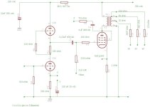
I did the same thing recently on a simple SE EL84 amp using a very cheap Chinese 5k output transformer. It resulted in about 6dB of feedback and these measured results (test signal directly to the grid of the EL84, measuring across an 8R dummy load, with and without the feedback):The Tubelab SSE board (a two stage stereo SE HiFi amp) has provisions to apply feedback from the secondary of the OPT to the cathode of the output tube. This raises the DF and lowers the THD a bit, but also seems to help squeeze a bit more bass out of a cheap OPT. No global feedback is used.
Attachments
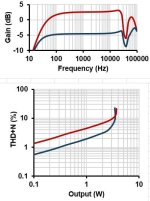
Worthwhile results and nice improvement. Thanks for the measurements.
Could you show exactly how you did the connection, preferably in a schematic?
Could you show exactly how you did the connection, preferably in a schematic?
- Home
- Amplifiers
- Tubes / Valves
- Strong local feedback + light global or the opposite?