Hi Guys,
Scored an Emotiva XPA-2 gen 1 power amp today for not much $
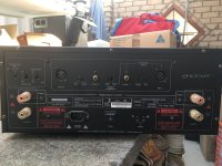
Issue is that it tries to turn on but goes straight into protection mode. So like any curious DIYer, off with the lid !
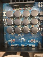
Jeebuz what a beast !! This thing weighs in at 35kg, has a 1200VA toroid and 12 x 15000/50V electro in the main pwr supply.
Rated at 300wpc these appear to be quite well regarded.
Anyways, I've pulled the DC power supply board but can't find anything that stands out as failed.
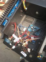
This thing has a soft start board that can auto select 120v or 240v and is also tied in with the protection circuit to open the mains relays if a fault is detected.
It is powered by its own 10va transformer.
Anyways, looks like it tries to power on, lights come on and relays click, then after 2 seconds, it shuts down.
This one is going to be tricky !
I've emailed Emotiva service but they have decided not to respond.
Does anyone have schematics for it they can send my way ??
Scored an Emotiva XPA-2 gen 1 power amp today for not much $
Issue is that it tries to turn on but goes straight into protection mode. So like any curious DIYer, off with the lid !
Jeebuz
what a beast !! This thing weighs in at 35kg, has a 1200VA toroid and 12 x 15000/50V electro in the main pwr supply.Rated at 300wpc these appear to be quite well regarded.
Anyways, I've pulled the DC power supply board but can't find anything that stands out as failed.
This thing has a soft start board that can auto select 120v or 240v and is also tied in with the protection circuit to open the mains relays if a fault is detected.
It is powered by its own 10va transformer.
Anyways, looks like it tries to power on, lights come on and relays click, then after 2 seconds, it shuts down.
This one is going to be tricky !
I've emailed Emotiva service but they have decided not to respond.
Does anyone have schematics for it they can send my way ??
Amp is up and running !
I did get schematics from Emotiva , which helped.
Recapping was just the start.
Turns out a faulty bias trip pot fault caused very high bias currents, which damaged the main PCB on the left channel.
Got all that sorted.
Anyone interested in this repair or need the schematics, let me know.
I did get schematics from Emotiva , which helped.
Recapping was just the start.
Turns out a faulty bias trip pot fault caused very high bias currents, which damaged the main PCB on the left channel.
Got all that sorted.
Anyone interested in this repair or need the schematics, let me know.
Yes Please!!!!! Mine is a Gen 2 with same type of problem on power board. When I attempt to turn it on you hear the relays click and see voltage led on rear jump to 230V when its connected to 120v. It promptly going into protect mode. I tried to Purchase the boards from Emotiva but they told me the 2 boards for power no longer exist. Loved amp so any and all info you could pass my way that might help me resolve my problem would be GREATLY APPRECIATED!!!!
Hiya,
It is normal for the 240v LED to illuminate until the voltage sense board figures out it is 110v.
The circuit for that is pretty tricky, but is all done by the soft start board ( which has the power relays on it )
Briefly,
With the amp plugged into power and the power switch on the back panel turned on, there is power available to the small 10W standby transformer.
This provides power to the soft start board and the protect / meter board.
If the front power button glows amber when the amp is powered up, this should verify at least that part is functional.
The very large 1200VA power transformer is NOT powered up at this stage. It has 2 x 110v primary winding's.
These are connected ( via relays ) in either series for 240v operation, or in parallel for 110V operation.
The relay you are hearing is the main power relay activating, and then turning off. ( because the protect module identifies a fault )
There are a number of ways that the protection can trip, and you will need to systematically go thru and find the cause.
For me, it was an issue on the left amp board, but I couldn't test anything because the protection shut down power to the main transformer ( which supplys power to the amp boards ! )
So I needed to remove the amp boards from the equation and trick the logic into thinking that the amps were ok.
Then I could at least test the power supply side of things.
************ Seriously, if you are not comfortable working with dangerous voltages the please DO NOT DO THIS YOURSELF !!!!!
To get access to the soft start board etc some disassembly is required
Main lid and rear panel off

power supply board ( the one with the big caps ) needs to be disconnected and removed.

the metal plate under that board needs to be removed

you can now see the soft start board

So what I did was to take +5volt from pin 3 on terminal K2 on the soft start board ( schematic PXPA-2 ) and feed that voltage into the L & R protect terminals 5 & 6 on connector K3 ( schematic AXPA-2 )

Making sure that all of the transformer secondary terminals are isolated from each other and the chassis, I then connected power, truned on the rear panel switch, an pressed the front panel button.
All LEDS turn red, and then once the protect board says all okay, 3 x front panel LEDs turn blue.
You can now measure the AC from all of the power transformer secondary windings. ( AXPA-2 )
If the amp now powers up, the fault is either on the main power board ( the one with the 12 BIG caps on it ) loose connector etc or on one ( or both ) of the amp boards.
The amp board has to output a voltage on pin 2 of the K4 / K5 connectors to tell the protect circuit that the amps are good-to-go.
If protect is engaging, then the protect board is NOT GETTING the ok signal via those circuits.
The problem is that if there IS an actual problem on one of the amp boards, and you FORCE power to be applied, really BAD things can happen !!!!!!
So, take your time.
Verify continuity along all paths of the protect circuit. ( my issue was a backed out terminal pin on the protect terminal block on the left amp board that was for the -38v supply. Simply refitting the terminal pin correctly in the board and re-soldering sorted that out ! because the protect circuit on the left amp board was now working properly and sending the okay signal down the "protect-L" terminal to the protect logic board.
This may not be your issue !

These little logic circuit connectors have a blue glue on them to prevent them from coming apart. They do take a bit of work to disconnect them. take your time and be gentle.

I was very lucky to find that !!
Good luck !!!
and be VERY careful
It is normal for the 240v LED to illuminate until the voltage sense board figures out it is 110v.
The circuit for that is pretty tricky, but is all done by the soft start board ( which has the power relays on it )
Briefly,
With the amp plugged into power and the power switch on the back panel turned on, there is power available to the small 10W standby transformer.
This provides power to the soft start board and the protect / meter board.
If the front power button glows amber when the amp is powered up, this should verify at least that part is functional.
The very large 1200VA power transformer is NOT powered up at this stage. It has 2 x 110v primary winding's.
These are connected ( via relays ) in either series for 240v operation, or in parallel for 110V operation.
The relay you are hearing is the main power relay activating, and then turning off. ( because the protect module identifies a fault )
There are a number of ways that the protection can trip, and you will need to systematically go thru and find the cause.
For me, it was an issue on the left amp board, but I couldn't test anything because the protection shut down power to the main transformer ( which supplys power to the amp boards ! )
So I needed to remove the amp boards from the equation and trick the logic into thinking that the amps were ok.
Then I could at least test the power supply side of things.
************ Seriously, if you are not comfortable working with dangerous voltages the please DO NOT DO THIS YOURSELF !!!!!
To get access to the soft start board etc some disassembly is required
Main lid and rear panel off
power supply board ( the one with the big caps ) needs to be disconnected and removed.
the metal plate under that board needs to be removed
you can now see the soft start board
So what I did was to take +5volt from pin 3 on terminal K2 on the soft start board ( schematic PXPA-2 ) and feed that voltage into the L & R protect terminals 5 & 6 on connector K3 ( schematic AXPA-2 )
Making sure that all of the transformer secondary terminals are isolated from each other and the chassis, I then connected power, truned on the rear panel switch, an pressed the front panel button.
All LEDS turn red, and then once the protect board says all okay, 3 x front panel LEDs turn blue.
You can now measure the AC from all of the power transformer secondary windings. ( AXPA-2 )
If the amp now powers up, the fault is either on the main power board ( the one with the 12 BIG caps on it ) loose connector etc or on one ( or both ) of the amp boards.
The amp board has to output a voltage on pin 2 of the K4 / K5 connectors to tell the protect circuit that the amps are good-to-go.
If protect is engaging, then the protect board is NOT GETTING the ok signal via those circuits.
The problem is that if there IS an actual problem on one of the amp boards, and you FORCE power to be applied, really BAD things can happen !!!!!!
So, take your time.
Verify continuity along all paths of the protect circuit. ( my issue was a backed out terminal pin on the protect terminal block on the left amp board that was for the -38v supply. Simply refitting the terminal pin correctly in the board and re-soldering sorted that out ! because the protect circuit on the left amp board was now working properly and sending the okay signal down the "protect-L" terminal to the protect logic board.
This may not be your issue !
These little logic circuit connectors have a blue glue on them to prevent them from coming apart. They do take a bit of work to disconnect them. take your time and be gentle.
I was very lucky to find that !!
Good luck !!!
and be VERY careful
Attachments
- Home
- Amplifiers
- Solid State
- Emotiva XPA-2 Gen1 schematic needed