Musings on THD

The total dynamic range of a THAT driver and receiver combo is over 21 bits, 20KHz bw, unweighted. They’re made for pro audio levels and systems. 128dB of DR is not reproducible in anything but a very special acoustic environment. However common mode noise down 75dB or so is.

You take your pick and apply technology that makes sense in the specific conditions.

IMO, bothering about THD below 0.01% is tilting at windmills because more than that is baked into all your recordings, and much, much more is added by your speakers. And it’s all masked by the music.
  • Like
Reactions: sawyers

Introduction!

Hey everyone! I guess this is my first post but I have been lurking for a while now. Thanks for all the information that you all have shared over the years! The speaker building community never ceases to amaze me! I have been building car subwoofers for a few years and recently started to develop more "Pro" level subs and have even made a few for "clients" after they hear my own system that I rent out at shows. Seems to be going well so far and I would not have made it this far without the community! I have also been working on my own full range horn speakers and got into 3d printing and CNC manufacturing to make my semi unique ideas come to life!

I can share some pictures of my designs if you are interested and maybe you can tear them apart a bit!

I do have a few questions for you all but I guess they can wait. Mainly regarding some DIY amps that while simple enough, are above my IQ apparently. I'll make a new thread for that possibly after some more digging!

Thanks!

Are any of the prebuilt amplifier modules on Amazon decent?

I'd like to buy one of the stereo amp PCBs that are on Amazon. I'd attach a sample but Amazon is crawling with examples, there are dozens of different offerings. The question is: Are any of them known to be at least "decent" in terms of quality?

I'm looking for a utility amp for the workshop and I'm thinking why not one of these modules? Ten or twenty Watts/ch is quite enough for me; but what's the trustworthy purchase? Thanks.

Aleph J cascoded three incarnations

Hi!

I made three types of wiring diagrams possible only to the precious advice of Zen Mod

1) Aleph J ZEN - IRFP150 - 30W

2) Aleph J ZEN - IRFP240 - 30W

3) Aleph J ZEN - IRFP150 - 60W

They have the front end as their common denominator.
1) type 1 is a 30W and has the advantage of being able to avoid MATCHING with IRFP150 that is equal of 2 x IRFP240 inside .
2) type 2 and 3 use the same PCB layout for both 30W and 60W (only the power devices, PSU and heat sink obviously change for 60W), both 24V to 32V RAIL able to operate.
Many thanks to Zen Mod
Antonio
  • Like
Reactions: Mikerodrig27

GB: EL34 Baby Huey Amp and PSU MK2 PCB

Hi. As discussed on the EL34 Baby Huey Amplifier thread, I'm starting a new GB for the amplifier PCB and separate supply, Mk2.

The AMP PCB is designed to install the tube from the back, version of this pcb is MK2 Rev 1.5-2, bottom, dated 14-07-2019, see schematic. The MK2 version has no power supplies built-in, you need the separate Power Supply PCB. As suggested I corrected R14/R15 to 1K/2W, the correct value for the EL34 tube.
You need One (1) AMP PCB per channel, Two (2) for a stereo amplifier.

The Separate Power Supply PCB is version MK2, Rev 1.5-1, dated 23-07-2019
You need one One (1) PSU for two channels...

Check the PCB images for dimensions.

Add your name to the list and send me a private email. Then I will contact you to get your full name, full shipping address and private email to reach you.
Once we have an idea how many members we have we can have an idea of the pcb price. Prices should be similar to previous GB...

We will see how it goes...Thanks
SB

March 19th, 2021 UPDATE
This GB is now CLOSED


March 20th, one kit still available, one buyer changed his mind...


July 12th, Will place a small pcb order this week for a few extra kits. Already sent email to the few that were interested so far. If interested let me know.


August 5th, Received second batch of PCB and already starting shipping. Still have a few extra kits, if interested let me know.
August 20th, Only one kit left, if interested let me know.

Finally ordered the output transformers for the amp, so I'll be able to test my own PCB. and received the power trnasformer as well.

Sept 9th, No more kit left, but I'm ordeirng a new batch with some other projects, so if interested let me know.
Sept 20th, received third batch of PCB and already starting shipping of two kits. if interested let me know.

Attachments

Coral BX-200 tweeter

Hello all,

First time poster, so please be kind and patient.

I've inherited a pair of Coral BX-200 speakers. They're going to be my first attempt at a refurb. However, one of the tweeters is blown, based on initial sound tests. Would anyone know where I could find a replacement? Or could I replace both tweeters with more modern ones?

Specs:

CORAL BX-200

Many thanks,

simao

Dayton4 - DIY Low Budget/Good Sound Small 2 Ways - With CNC Enclosure

DAYTON4 - BUGET SMALL 2 WAYS

ORIGINAL DESIGN BY DUANE BROWN

You can find his design including original enclosure size, crossover components and everything related on Mr Duane Brown page:

https://duanebrowndesigns.blogspot.com/2018/10/getting-your-feet-wet-in-diy-speakers.html?m=1

You can also find the several reviews and variations on this design on several forums...including good comments from really good speaker designers, and also for the Dayton Audio TCP115-4 4” woofer that is used on this 2 way speaker known by the bass it can produce.


The reasons to choose this design where easy:

*A small 2 way with flat response, details and clarity. There is plenty of images with the frequency response and such.
*Components where cheap…i´m in south america so shipping cost are also take in account.
*Few components crossover… i read/think too much about the changes that every electrical component/equipment adds to the sound, this is a series crossover, only 4 parts.
*Small size and Area to be fulfilled… Just a small living room.
*Good reviews for design and components… from designers on other forums and the drivers itself on youtube.
*They are been made as a gift for my Dad (73)…so he doesn't need to get a Beryllium tweeter either way (Even when he deserve it..i cannot afford it)
*Also for my to compare it with a full range MarkAudio speaker that i build on planet10 mFonken enclosure that i REALLY like as was my first diy speaker and i'm still impress on how a good FR driver with no crossover whatsoever sounds that good.

DRIVERS:
Woofer Dayton Audio TCP115-4 4”
Tweeter Dayton Audio ND16FA-6 5/8”

CROSSOVER:
3 OHM 10W RESISTOR
0.20mH 18 AWG COIL
8.0uF CAPACITOR
1.0uF CAPACITOR

ENCLOSURE

I do changes in the cabinet outside dimensions, trying to apply the theory on Direct Radiator Loudspeaker Enclosures by Olson Harry.. also to impress my Dad on what carpentry with cnc can do now days.. the internal dimension where the same that other builder used on Mr Duane design and call it the ¨Deluxe version¨ as he made it a litter bigger and change the crossover components to polypropylene versions on the capacitors. The original enclosure is 8” tall, 6”wide, and 8.5” deep.
The enclosure material is 18mm pine plywood, lining the internal walls with recycled denim, the material used on car trunks/carpets.

I think i don't have anything more to cover so here some pictures of the build process=


FLAT PACK..To call it in that way

20241202_154828.jpg


20241202_154711.jpg


20241202_154805.jpg

The letters on the top are my dad´s name initial..in case you are wondering


Baffle -- recess cut for driver to be flush mount and release on back to let it flow

20241202_165258.jpg


20241202_165249.jpg


Binding post cut manually done, as the cnc guy ¨forgot¨to do it...not finished in this photo

20241202_165217.jpg


Glued together - I'm missing a photo with the internal material--next time i post

20241202_174150.jpg


20241202_174201.jpg


Crossover assembly - testing - finished

20231206_174314 (1).jpg


20231219_150253.jpg


and the Ufoken enclosure with Markaudio CHR-70.3 that i did as my first diy speaker that i want to compare against this 2way design

ufoken.jpg


I will post more picture as i progress with the process.. hope this week is going to be complete already.
And by the way English is not my native/first lenguage in case it wasn't noticed

Hi everyone. I,m sure I’ve posted on here over the years but just had to reset password

I was in the audio industry for quite a few years. I am both an audiophile who enjoys music on my modern gear, but love my vintage 1970s, 80,s gear even more. I have restored many amps, cassette decks, reel to reels, etc. and have lots of Teac along with other Japanese brands.
  • Like
Reactions: Freedom666

KiCAD Kick start

During the last few years I have been playing a little with KiCAD and have some drawings of more and less well known commercial designs, as well as designs from diyAudio and other forums. Many boards have been routed and a few have been produced. So far, some are being built, but only the Pioneer Superlinear has been tested by a friend of mine. Worked fine.

Now I wonder if someone is interrested in a KiCAD Kick start (I know I would, when I started) by exploring my KiCAD project folders? You may download everything or just a little. Use it, misuse it, alter it.... no copyrights on my part.

What I don't know is if there is a time limit or download limit to these Dropbox links. Anyway, we'll find out.

If the interrest is there, I will post the link.

A few samples of produced PCBs:

Order_02_C.jpg


Cheers!

🙂 morten

Fixing a high end record player, a Fischer Price 820 !

Today, an unusual fix (for hifi aficionados like we are), a Fischer Price 820 toy record player.

Someone brought it to me, not working. Not producing any sound from the speaker, more precisely. This machine can work both with 4 C 1.5V batteries and with a 6V DC external power (+ inside). That’s the reason why he took it to me. He had tried to power it with an external PSU, but not knowing its voltage nor the polarity of the plug. Therefore, it has produced a plop and smoke when he lifted the arm up.

The motor works, the platter turns when you lift the arm (like it should), but that’s all I know.

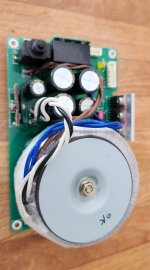
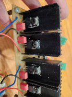
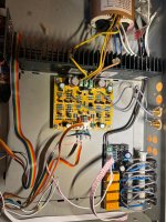
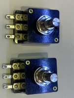
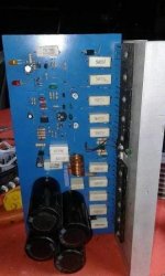
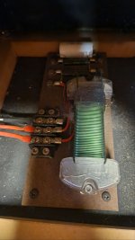
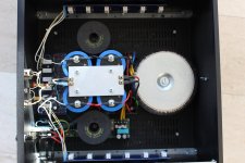
First, 5 screws to open the plastic case. We can see a small PCB, two contact relays, the (small) motor, and that’s nearly all you get inside. Which is enough. Everything else is plastic, rather good quality one. A robust toy.

1736177737642.png


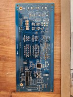
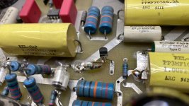
On the component side of the dirty PCB, I see immediately the 220µF/10 capacitor which has blown up (center of the photo below). Easy. That size, only got a 470µF/16, it will do. Reflowing some solder joints, little bit of PCB cleaning, resoldering all wires. Give a try, not working. Ah.

1736177824537.png


It’s more complicated than I thought. Got to investigate a little bit more. I like it, kind of too simple if there's no sweat at all...

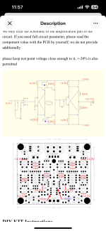
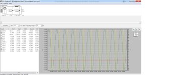
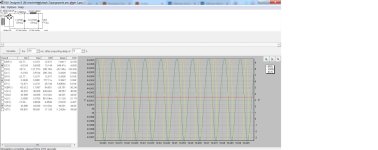
First, try the speaker on its own. It works. Then going backwards, I injected a 100 mV 10 kHz sinus signal on the PCB points corresponding to the red and black wires coming from the piezo pickup and I could hear some sound coming from the speaker. So at least I knew that the amplifier part of the circuit was OK.
So the problem was 
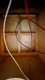
probably with the wires from the pickup to the PCB themselves. And it’s the tricky part, because to access to the pickup wires is rather uneasy, to say the least.

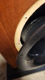
I had to unsolder the two wires on the PCB to let some room to get the arm out, then take it out (circlips, platic parts and so). This step is rather uncomplicated. Next one is more challenging. Once I had the arm apart, obliged to cut delicately between the superior and inferior plastic parts of the arm with a cutter to separate them and access to the pickup connections themselves (no screws, sorry). Continuity was OK through each wire, but. But of the 2 contacts of the pickup itself to one of the wire, no continuity.

There is a small metal contact linked to the wire that is supposed to make contact with the pickup.

1736177898111.png


One of them was not bent enough to be able to touch the pickup contact. I bent it more with a very small plier, and then, there was continuity again. I tested roughly with my finger gently brushing the tip, and I could hear a sound from the speaker. OK, I like that better.

After I cleaned all the moving parts in the arm and greased them lightly, I glued the inferior and superior parts of the arm, reinstalled the whole thing back, and had a try with a record. Everything was right, nearly good sound. Tuning of the 45rpm and 33 rpm speeds with the two dedicated trimmers, general cleaning, screws back.

video Fischer Price 820 (YouTube)

That’s it.

That post helped me a lot : fisher-price-816-record-player-repair
  • Like
Reactions: phase

Best Practice for measuring burst decay

Hi All,

How do you measure bust decay? what are the best practices?

I am using a measurement mic and the REW Spectrogram tab set to burst decay.

I am measuring indoors. (probably a red flag)

I have tried measuring at 50cm, the burst decay is full of noise from room reflections,
I have tried measuring at 5mm from dust cap, there are no resonances visible (I'm pretty sure the enclosure has some resonance)
I have tried measuring at 5mm from the side panel, room reflections dominate the signal and no resonances are visible through the noise.

Do I need an anechoic chamber or an NFS to do this? or is there a clever way of doing it indoors? I have also considered buying one of those portable power station things and taking the measurements in a park, away from all reflective surfaces. The last option doesn't sound very fun, especially as I am trying to compare 4 enclosures using the same drivers so I will be pulling speakers apart in a park...

Thanks in advance for your help,

For Sale Oppo UDP-203 Linear Power supply Upgrade, 115V version

FS original UDP-203 Linear upgrade power supply, 115V Version, assembled and tested, bought directly from https://www.oppomod.com/

Replace the original Oppo switching power supply, to eliminate all the HF noise induced by the Switching supply, for better audio and image quality. Easy to install, just remove the original supply pcb, screw in and connect the new supply, piece of cake...

Still sell for 360U$, see https://www.oppomod.com/

Asking 200U$ + shipping + Paypal 3.5%

Attachments

  • 20250109_132219.jpg
    20250109_132219.jpg
    122.8 KB · Views: 55

First Watt Modules Concept

I'd like an amp rig that's based on swappable circuit modules that you can "roll" like tubes. DIY First Watt circuits are an obvious choice for this concept as there are so many circuits to choose from. Other circuits will be great too, JLH, etc. If I create formfactor for this will Papa disavow?

Server rack or maybe Eurorack with pins would be a general concept. For example, a 1U chassis with active cooling, universal PSU and swappable amp/preamp circuits.
  • Like
Reactions: von Ah

Fully digital DC to DC converter XL4015 based

For those who looking for something like this

Attachments

For Sale Borbely Phono PCB EB-804/419, and All-FET Low Noise Regs EB-707/418

For sale, Borbely Borbely Phono PCB EB-804/419, and All-FET Low Noise Regs EB-707/418, The phono is a two sections, MC front end, and then MM section, all similar using the now well known K170/J74 front end JFET, AD820 Hi-end op-amp for servo, all vishay resistors, Wima cap, etc. A great phono section,

and as for supply the all discrete All-FET Low Noise Regs EB-707/418, with as for final the famous K2013/J313!

Two pcb comes fully assembled and tested, bought them some years ago from an other member.

Asking 175U$ for the phono section and 100U$ for the All-FET regulators + shipping and 3.5% Paypal fee

Just with the cost of the pair of K2013/J313 is it a very low price!

You just need a power supply and enclosure for a killer phono section.

Kit comes with all the docs, schematics, Borbely articles, detailled BOM, etc...

Attachments

  • 20250108_195539.jpg
    20250108_195539.jpg
    332.7 KB · Views: 137
  • 20250108_195554.jpg
    20250108_195554.jpg
    322.2 KB · Views: 115
  • 20250108_195608.jpg
    20250108_195608.jpg
    253.1 KB · Views: 124
  • Phono_Schematic.JPG
    Phono_Schematic.JPG
    123.2 KB · Views: 134

New Pro audio guy saying hello

Hello everyone. First a little background on me. I’ve been into audio since I was a kid. From playing guitar with my grandpa to getting my first boombox to modifying audio in my first vehicle. This lead me to a career in car audio a job that I loved and then lead to me doing live sound. I now run production for bands and DJs and am here hoping to learn more. Mostly in the PA realm but other things as well.

Greetings from the 'burgh

Hi all. My background is mainly in software and audio recording/production, but I started my career in electronics and have always like circuit design and anything related to audio especially with guitar amps since I used to also be an avid guitar player. While troubleshooting an issue with my guitar amp recently, I came across this forum and not only are there a vast array of topics on this forum, I was very happy to see that it is a helpful community also and looks like there are many members willing to share and help each other out.


-Brandon

Hello All

New member here. Thanks for the add. I'm also new to diy audio repairs and audio gear collecting. I'm currently listening to mostly vinyl on my SL 1600, running it through a NAD 1240 preamp into a Sansui 5000A. I'm still figuring out the speaker situation. I currently run Sansui SP-3000's on A, pioneer cs-66a's on B, and am rotating some Bose 6.2 or Minimus 7's on C. I picked up a pair of Pioneer cs-05's that weren't great. I'm redoing them with all new drivers and some refinishing of the wood, because I think they look cool, but I'm skeptical that they'll sound great.
Anyway, I appreciate the admission to the group.

How to connect speakers to powered mixer for synths at home?

I was given a Peavey XRD 680S powered mixer and one SWR Big Ben passive subwoofer (19" 8 ohm). Planning to give them to a friend who's got a couple keyboards & a drum/bass machine. Just for his own basement amusement, not gigging. I have some noob questions about setting this up, as I'm just a guitar dude.
Since the instruments all have L&R line outs, I'd send each side of each instrument to its own mixer channel panned all the way left or right. There are 8 channels. Is that how it's done?
We don't have a pair of monitors. Would it be ok to plug the mixer's 'tape outs' into a hifi 'tape in'? It'll be a raw peaky signal and I'm wondering if we need to run it thru a limiter.
For the Big Ben, my plan would be to run it off the mixer's main speaker outs and use the mixer's graphic EQ as a low-pass. But, to sum the left & right power amp signals, is it safe to use a Y adapter? And since I'm looking for 8 ohms, would I use one output per side, or do I have to sum all 4 power outputs? The mixer has 4 quarter-inch speaker outs (2L & 2R) labeled: "105W/8 ohms, 150W/4 ohms, 30V RMS min amplifier load, 4 Ohms each channel". Here's a pic of the most heavy duty 1/4" Y adapter I can put together.
And please let me know if I missed any other major issues. Thank you!
Y adapter.JPG

QCC5125

May I ask for help? And I really hope someone can help me. I have a bluetooth module (QCC5125).
First I programmed it to rename and set equalizer, it worked. Then I tried a second time, maybe I had the wrong program or whatever, and now my Bluetooth module can't be read on the cellphone, but it can still be read USB Port on the computer. Does anyone here have a dump file for this Bluetooth module?

Attachments

  • images (12).jpeg
    images (12).jpeg
    48.4 KB · Views: 54

Yet Another Soft Start Circuit

After looking at a bunch of soft start circuits I decided to design one according to my beliefs as to what is the best way to do it. It may be completely different from your beliefs but there it is.

I wanted a separate power supply for the soft start circuit so it could be used to turn the amp on and off and the powering up of the amps large transformer would not interact with the circuit. The transformer has a dual primary so it can be used for 115 and 230 VAC. There is a surge suppressor, R1, across the transformer input as well as a small high voltage capacitor to filter out RFI on the line from coming into the amp. The power supply always draws a few milliamps, it powers a multicolor LED that emits red with the amp in standby.

The on/off switch only switches 15 volts DC at very low current so you don’t need a switch that can handle large AC current in-rushes. When switched on, the DC power is sent through a regulator for consistent voltage and time of circuit operation. Relay K1, a small current relay, pulls in and turns on a triac, AC current flows through a couple thermistors in series to limit in-rush current, two 5 Ohm parts for 115 volts to limit the current to no more than 12 amps, or two 10 Ohm parts for 230 volts also limiting to 12 amps. There is a current limiting resistor, R2, at the triac gate and a RC network,R3/C2, over the triac for some protection of the triac.

The circuit uses a voltage comparator, U2, to delay turn on of a relay, K2, which bypasses the thermistors, I do not like to have a current limiter staying in the circuit or the heat they generate inside the amp. The voltage comparator has a voltage divider, R8/R9, to set the voltage at 10v as the reference voltage on the positive input. That voltage is compared to the negative input which has an adjustable resistor, R7, which limits the current charging the capacitor, C6, and the rate of charge therefore voltage ramps up quickly, a couple seconds to more than 10 seconds, for the delay. When the voltage on the negative input matches the positive input, the output is turned on. There is a diode, D4, across R7 to give a quick discharge path for C6 so the circuit can reactivate quickly, as in the case of a temporary power loss. R2 limits the current through the comparator which drives the gate of a small MOSFET through a gate resistor, R11. The MOSFET pulls current through a large relay K2 to bypass the thermistors and another small relay, K3, which changes the LED from red to blue to show status ON. There is a Zener diode, D5 and a small capacitor,C7, at the gate of the MOSFET to protect and stabilize it, probably not needed but cheap insurance.


So far, the circuit has been very reliable in a couple power amps with 2400VA and 4000VA toroid transformers with .78 farads to 1.2 farads of storage caps. In small part quantities the soft start board costs around $34 USD.
Attached is the Schematic, BOM and Gerbers. Enjoy.

Attachments

For Sale Oppo UDP-203 Upgrade kit - 2CH version, ES9038DAC chip

FS Upgrade DAC kit for the Oppo UDP-203 Player, This kit includes a new Audio Dac board -2 CH version, specifically designed to replaced the original Oppo Audio Dac section with ES9038 DAC, with new Firmware.Includes the PCB, custom firmware controller and all the parts, schematics, detailled BOM, etc.

This project was developed by one of the forum member, and the PCB/controller/Dac was sold some years ago. This kit is complete, and 100% compatible with the Oppo, just assemble, and replace the original DAC board.

These mods are still offered by: https://www.oppomod.com/, cost near 1K$...

NOTE: this is the 2CH version of this upgrade, meaning your Oppo player will have only 2Ch audio outputs after the upgrade!

See also my Oppo 203 Power supply upgrade board, all assembled and tested. original cost 280U$ (357$CAN once shipped to me...)

Asking 200U$ + shipping + Paypal 3.5% (Original price was 500U$!)

Attachments

  • 20250109_130610.jpg
    20250109_130610.jpg
    450.9 KB · Views: 59
  • 20250109_130616.jpg
    20250109_130616.jpg
    531.6 KB · Views: 58

NAD 521 with "audio modification"... worth buying?

Hello everyone,
I need a bit of advice. I have the opportunity to buy a NAD 521, which was revised and got an "audio modification" in 2015. The seller asks for €75, with p&p I will end up at around €85 (roughly $90). Its unclear what this "audio modification" means, the seller does not know. I attached a picture from the PCB. The Display looks rather dim on the pictures the seller provided.
Is it worth it? Ist the price okay? The device itself looks very clean and without any damage. I know there are quite some versions of the 521 around, with the plain 521 being the oldest. Should I look for a 521 BEE, which will be around €200 in my area?
I am looking for an affordable, good looking "vintage" CD Player with robust mechanics which can be upgraded with better components. The motivation to do this is more to learn a bit and just for the fun of modding. I do not expect to create something real high-end.
Cheers, Robert
Bildschirmfoto 2025-01-06 um 14.09.46.png

Hi from a new DIYer

I'd rather build than buy. I'm currently working on an SP-14 preamp from Vacuum Tube Audio and a Gainclone. After those are finished my signal path will be entirely home built other than the SL1200 (which is not without mods). I'm looking forward to seeing what everyone else is working on.

Here's a dual mono Emerald phono preamp from RJM audio that I recently built. The chassis were old serial KVM switches with some figured maple to add some flare.

20250108_164516.jpg


20250108_164601.jpg

Hello World

Hello all,

I'm Kalle from Germany; event technician and building bass cabinets since the early 90s or so...
Bought AJhorn last year and am now mostly using Hornresp instead ;-)

Thanks to this forum and others I built two 15"-tapped horns last year which work very good. Next project are some 18" br/TL-horn-hybrid speakers.

Greetings!

Kalle

7.4V (5V) Battery Power Supply with Aliexpress parts

Hello, recently looking into all sort of battery power supply solutions

for starting out and getting some kind of reference to go from i wanna build something similar to this one: https://www.aliexpress.us/item/1005005947064087.html for 5V output

consisting of these parts:
https://de.aliexpress.com/item/1005005965787184.html (outputting 5V)
https://de.aliexpress.com/item/1005006246781194.html
https://de.aliexpress.com/item/1005007103958671.html
https://de.aliexpress.com/item/1005005727166588.html
4x Molicel P26A 18650 Cells in 2S2P configuration
2 Switches (like the LHY power supply), one for charging one for load

gathering mainly from google or youtube this should work out just fine 🙂

Speaker fell over, now not working. Help

Hi guys. I have a pair of Townshend Glastonbury speakers from the 1980s. They have been in regular use with no problems.
Well I accidentally nudged one of them and it fell over on its side onto a wooden floor.

The ribbon tweeter still works but the midrange doesn't. I believe it is a Jordan J125 or J150. What should I be looking for? I have the crossover and the driver unscrewed but can't see any dislodged wires. The crossover board seems intact.

What should I be looking for?
Thanks, Stephen

AD1862 vs AD1865

I have a ANK DAC 4.1, which uses a CS814=>AD1865 implementation.
The cheap USB input board failed, so I was planning to replace it with the XMOS based I2SoverUSB board.

But I also thought.. since I am at it, why not replacing the whole DAC board with a XMOS => AD1862 implementation.
The new design would use dedicated separated supplies for the digital and analog sections, and the outputs of the DAC chips would be directly connected to the I/V transformers that drive the original tube output stage, as per original audio note design.

Long story short.. anyone who has experience playing with the AD1865 and AD1862 would suggest one over the other?

Thanks,
Marco

Save your Transformer, always use an Artificial Center Tap on your heater windings...

Greetings, friends. Today I was hoping to spark a brief discussion on proper heater wiring. This idea came from an Instagram poster known as Amptech74 who repairs guitars and tube amps and probably seen more violently explosive tube behavior than most of us in Hi-Fi land, with the notable exception of @Tubelab_com.

Anyway, here's the idea: don't use the Center Tap that's hardwired into the power transformer. When a power tube fails, the plate voltage is going to find the easiest path to ground. If the plate arcs to the cathode, it still has to go the cathode resistor to get home, but if it arcs to the heater, it only has to fight the resistance of the copper wire. If that voltage happens to pass thru the power transformer, well, there's gonna be damage. But if you are using an artificial center tap, the HV can only cook those 2 resistors, saving your expensive iron.

So. Waddya think?

w

Hello from new member in NJ

Hello. I am actually an old member of diyAudio but I stopped pursuing this passion for > 10 years and I am not able to recover my old account here. I am a EE nearing retirement age. Most of my career has been spent working on Naval aircraft engine controls with focus on software and electro-mechanical systems. My circuit design knowledge is circa 1985. I was also a dedicated speaker builder for close to 20 years but also stopped that when family and job started taking most of my time. I am getting back into this hobby with plans to recap/revive an Apt Holman One amplifier and some Soundstream D100 and D200 car amplifiers. Hopefully, I will have some knowledge to contribute as I get more involved.

Upgrade from here

Hey everyone. I do live sound production and provide sound for both DJs and bands in many different indoor and outdoor venues. Anywhere from 100-1000 people.

I’m looking for a PA that can accommodate these shows with good results.

I’ve used some of the upper end of the prosumer market in the past and although had decent performance was not quite able to hang at larger events.

I’ve had Yamaha DZR 12s and had them hitting limit at larger shows. I also had one of them die during a show and ended up having to send it in for repair of a blown transformer on the board. A friend of mine also has owned dzr 10 speakers for monitors and has had to send them both in for repair of similar issues. Great warranty but need better reliability than this.

So what’s considered the next step from here? Something over a the DZR SRX series that can push a bit harder and not cost triple the price?

Is it possible to get better than this without spending that much more or does the price just go up significantly after this point?

I’m open to powered or passive options whatever will get the job done best.

Thanks for reading and I appreciate all of your input.

“Bumpy” or Variable Depth Driver Chamber - Method?

Several times I have seen Scott and others recommend certain optional improvements or tweaks for speaker enclosures, one of which applies most commonly to back horns with shallow driver chambers. The idea is to move the rear surface of the driver chamber backwards (making the chamber deeper) but then displace the extra volume with many blocks of various lengths of wood, randomly, so that the rear chamber wall becomes “bumpy” but the chamber volume remains the same as the specified chamber volume.

For the life of me I cannot recall what this is commonly referred to as, and I am therefore having difficulty finding the method to accomplish this accurately. I would obviously begin by calculating the volume of the standard driver chamber (as designed). Easy enough. What is the simplest method to achieve the desired result?

Need help about filament noise

Hi . I have a sharp md-xv300 . Original transformer is dead . I replaced a transformer all voltage needs is same except that original transformer has a separate 30v for running filament screen . I have extra pins with 12v and also 25-0-25v that used to run amplifier chip. Screen works with both on 12v i have very load noise and low light screen and on 25v screen brightness is ok but it has also noise but lower . I'll be thankful if there is a solution to solve or reduce noise . Thanks 🙏

For Sale Geloso G-227A EL34 PP mono amplifiers

A few months ago, I came across a beautiful set of Geloso G-227A tube amplifiers and felt inspired to breathe new life into these rare gems. After a careful restoration, I’d say they’ve come back to their full glory!

I’ve restored them with precision—replacing old capacitors and resistors, adding modern RCA connectors, and upgrading to contemporary speaker terminals. Their vintage casings remain beautifully intact, with just a touch of wear that gives them that authentic retro vibe.

Result is a dynamic and detailed sound thanks to fine-tuned gain stages and high-quality transformers. Powered by brand-new RFT EL34 tubes, they offer a great listening experience.

There is a switch that bypasses all the controls and you can use them as power amps. If in another position, you can use them with their original inputs.

Price is 1100€. We can negotiate and I do accept some trades. Location Croatia.

Regards

Attachments

  • 3_with_bgc.png
    3_with_bgc.png
    1.3 MB · Views: 818
  • 4_with_bgc.png
    4_with_bgc.png
    1.4 MB · Views: 627
  • 7_with_bgc.png
    7_with_bgc.png
    1.8 MB · Views: 693
  • 1_with_bgc.png
    1_with_bgc.png
    1.9 MB · Views: 141

Shanti Dual LPS 5V/3A , 5V/1.5A

Hello ladies and gents.


Music and linear power supply has been always a good match . The main problems of LPS is extremely inflated pricing and no data.


You see not all LPSes are equal . Just using a transformer will not automatically give you a better PSU. Worst is that most of manufacturers include no testing . no data that can help chose one.


We mean to change that.


First we started with the transformer . There are many types of transformer , some are worst than others (noise coupling , electromagnetic interference)

We chose one of the best transformers for noise ,r-core


The transformer has a dual output (galvanically isolated ) so you can power multiple devices (RPI + dac , Katana , etc) and we used independent (of course since they are isolated) filtering on each rail. First a capacitance bank (massive) to reduce the 50/60Hz noise , then a active filter , fallowed by an LDO to keep voltage stable . Since LDOs have poor transient and impedance , we used a last active filter (with good transient) and then capacitance but most importantly , super capacitors on the output . So all power comes in fact from supercaps..So yes , transients and impedance of the LPS is..good.


Of course , Shanti includes AC line filter and AC is earthed to casing.


A few words on what we achieved . Measuring noise (in real word scenario) we see about 80nV (0.08uV of noise from 0-20Khz at the floor of our AP machine. This is comparable to batteries from our internal testing .


As explained , Shanti is not only shining because of the ultra low differential noise, but also because of incredible low impedance / deep reservoir of electrons at the output of the PSU ( thx you soundcheck for your suggestions )


At last ... pricing . We are working very hard to make this LPS the lowest priced on the market . All components are on the way , it will take a few weeks to start accepting orders. Questions and comments are welcomed

Attachments

Insulators for parts passing through aluminum heat sink? Bolts for TO3 devices?

Hello there,

I get that you use a TO3 insulating pad under a TO3 device so you don't short it out to a heat sink if it is mounted on top of one, but what insulators do you use around the leads/bolts passing through the heat sink?

What type of fasteners are commonly used?

What would be a a good "broad" insulator to use between the board the the heatsink?

Here is an example of what I am talking about,

Thank you,

David.

Attachments

  • Quad 606 board trans mounted.jpg
    Quad 606 board trans mounted.jpg
    96.4 KB · Views: 195

Pass Labs X1 volume control probelm

I have a Pass Labs X1 preamp, and I’m currently facing an issue where, at volume level 3, the left channel suddenly goes to maximum loudness. During troubleshooting, I swapped the volume control board with the right channel, and the problem followed the board. This confirmed that the issue lies with the volume control board.


After further testing, I identified that Q3 on the board is the faulty component. It’s marked as “8F” and comes in an SOT-23 package. However, I haven’t been able to find much information about it. Could you help identify the exact part number for this component?

C3850 Little construction project

I have been building a little pre-amp from an eBay pcb which is based on a 3850 circuit been going well and have fitted it into an old NAD chassis and using f the NAD volume pot. Which turned out to be way too low at 20kohm. I tried replacing the 5532 with a 4562NA however this oscillated producing a ticking noise. the 5532 was tick free. I added 47k in front of the pot to give it some actual volume adjust ment but I may need to change it for a new one. At the moment I have a 50hz hum issue to deal with once the volume heads towards 1/3rd I am wondering if this is the filtered iec I let at the moment. But hum aside it does sound very good way better than my old cyrus

Attachments

  • IMG_2696.jpeg
    IMG_2696.jpeg
    1 MB · Views: 160
  • IMG_2697.png
    IMG_2697.png
    621 KB · Views: 152
  • 7401F3E8-C9F3-4C5E-9CB0-055E8F3F8B31.jpeg
    7401F3E8-C9F3-4C5E-9CB0-055E8F3F8B31.jpeg
    491.7 KB · Views: 153

2 TKD (big) potentiometers, 50K log taper .

Hi. I have a couple of pairs of the gorgeous TKD 50k mono potentiometers (Volume controls) for sale. These were used in a volume control shoot-out in a multi channel system. They are in near mint condition. The input, output and ground connections have been carefully desoldered and cleaned. I would like $85/ pair, shipping in USA included.

Attachments

  • 0FC2AAE4-CBF1-4A75-8D5D-582A00F5DA7E.jpeg
    0FC2AAE4-CBF1-4A75-8D5D-582A00F5DA7E.jpeg
    507.7 KB · Views: 274
  • 31530EDC-F385-486B-AE6C-4AA24FD03D73.jpeg
    31530EDC-F385-486B-AE6C-4AA24FD03D73.jpeg
    318.1 KB · Views: 276
  • 5EFE5CBD-BE78-469C-B281-CC30B4156C5F.jpeg
    5EFE5CBD-BE78-469C-B281-CC30B4156C5F.jpeg
    403.9 KB · Views: 267

Replacing pots in Infinity RS-II crossovers

Hi all, quick question. My crossovers have 2 pots each to adjust highs and mids. One of the mids pot is completely shot and the other one reads funky. Tweeter pots seem OK but they're 42 years old.

According to schematics, all pots are 5 ohm 5 watt:

RS II technical manual.jpg


But in real life, they're clearly different. Folks say the mids pots are 15 watt and the tweeters 5 watt, and that looks plausible:

pots.jpg


My first thought was to just replace the old pots... but audio grade 5 ohm 15 watt pots only appear to exist in Australia

So now I'm considering replacing them with fixed resistors, since their utility is debatable to begin with.

I tested them (out of circuit):
  • Tweeter pots measure 2.5 ohm at midpoint and 5 ohm all the way down, so that's all good per specs
  • The one mid pot that sort of still works measures 3.4 ohm halfway, and 5.7 ohms all the way down. The other mid pot is too far gone to measure anything.

Now for my questions:
a. That mid pot's 3.4 ohm halfway to 5 ohm read doesn't match a known taper. Is it fair to assume it was linear when new, and it just drifted over the decades?
b. I want a "flat" response, so I'm thinking 2.5 ohm fixed resistors (assuming those mids pots are in fact linear). As far as power rating, it's tough to find 5 and 15 watts in the same series but Dayton makes 2.4 watt, 1% wirewound rated 10 watt and 20 watt, so I'm leaning that way and it won't break the bank. Still, it would mean a significant increase in power rating over stock
c. I've done a bunch of reading about whether increasing resistors' power rating can affect sound quality, and the consensus seems to be that it won't make it worse and it might even make it a little better. Do you guys concur?
d. Now we're splitting hairs, but I gotta ask: my new fixed resistors will probably have much lower inductance than the pots they replace. Does that mean anything in terms of sound quality?

Thanks!

2SC5200 fake or original?

According to the seller only tray pack has 'Japan' marking on 2sc5200/1943 transistors & there is no mention of 'Japan' in the strip pack(see attachment). I believe these are 100% authentic, what do you think? 🙂
Best Regards!

Edit:- These aren't original but good quality chinese copies. My apology to everyone.

Attachments

  • FB_IMG_1638263085197.jpg
    FB_IMG_1638263085197.jpg
    66.5 KB · Views: 1,122
  • FB_IMG_1637922393308.jpg
    FB_IMG_1637922393308.jpg
    45.1 KB · Views: 1,610
  • IMG-20211126-WA0000.jpg
    IMG-20211126-WA0000.jpg
    59.6 KB · Views: 1,054
  • Like
Reactions: asuslover

Common Ground Collector amplifier

In 2017, I built this amplifier for my brother's audio system. It is a single common grounded collector amplifier based on RMX series of QSC.

Supplied with +/-80V, I added five pairs of transistors for output stage. It is very stable once the bias adjustment is set properly. The input opamp is very important to be good quality and check +/-15V rail supply to be as simetrical as possible. I wanted to keep the same subsonic filter to cut off frequencies under 30Hz and 50Hz.

The sound is very good however I was designing a PCB with smaller size. Thanks

Attachments

  • 1736241908159.jpg
    1736241908159.jpg
    64 KB · Views: 221
  • 1736241919037.jpg
    1736241919037.jpg
    84.5 KB · Views: 188
  • 1736241914986.jpg
    1736241914986.jpg
    26.1 KB · Views: 96
  • 1736241930355.jpg
    1736241930355.jpg
    83.1 KB · Views: 88
  • 1736241923626.jpg
    1736241923626.jpg
    63.6 KB · Views: 222
  • Like
Reactions: luis401

Onkyo Integration TX 870 issues.

Hello. I’m working on my TX 870 and having a few issues. The left channel dropped out and the main fuse blew. I found a cracked bridge rectifier and it was toast. Replaced it along with all the outputs on the left channel. Found some bad transistors on the main board and also replaced the drivers. For some reason I’m getting full rail voltage at the VCT test pin. This won’t allow the protection circuit to close the relays. It should be in the millivolt range. The right channel is fine. DBT goes bright as the main power relay closes and then opens and the DBT goes dim. Constant cycle. I’ve got the service manual and have replaced the emitter resistors, and several other bad components that tested bad. Any ideas ? The output transistors are fine. No shorts. Thanks in advance. The only other thing I replaced were the 2 caps in the protect circuit.

looking for info from diy member featured on youtube

hi forum
i've just watched a video on the steve guttenberg youtube channel featuring a gentleman called joe who is into horn speakers, he referenced this forum in the video.(the video is from 5 years ago)
in the video he briefly touched on the design of his subwoofers, which use two speakers working opposite to each other and facing in opposite directions. i'm hoping that this subject has been discussed already and that someone could point me to the correct thread, or even plans and theory for this subwoofer.
this is the video -- Login to view embedded media
any info is appreciated
gaz

Single drive full range: the bug has bitten

Hey everyone, brand new member here who will probably leech more information than contribute given my complete lack of electrical/acoustic intellect (drummer, go figure). In fact, I never thought I'd be reading much less typing messages to this group since I've always been an OOTB audiophile musician gear-collecting type, albeit single-driver-curious, but that seems to have changed last week:

  1. Finds pair of Fostex fe206e-loaded cabinets for $100 on fb marketplace and says screw it why not
  2. Plugs them into garage "tester" setup (Arcam receiver, Meridian Explorer portable dac), sounds like crap
  3. Removes the reflex port to discover there's some sort of crossover network thing, bypasses it, listens again, ok now we're going somewhere interesting
  4. Swaps them into the Rogers LS3/5A livingroom setup (Naim entry-level separates, Bel Canto 1.5 dac), and despite flaws, there's something alluring that bears more exploration
  5. Swaps them into "reference" DeVore Gibbon Super 8 system (Naim Supernait 3 integrated w/ HiCap DR, Rose RS150b streamer/dac), hasn't left chair for 5 hours (other than to make dozens of adjustments to speaker/listening position). Oh, and signs up for diyAudio account 😉

Wow. As absurdly, unfathomably finnicky as these things are about placement and amplification/sources, there is a magical palpability and image that, until now, I've only heard others talk about with their setups, or have only heard myself on (some but not all) six-figure setups at shows.

So, this is all to say I forsee myself spending hundreds of hours scouring this forum for tweaks and advice, of which there appears to be no shortage of, and will thank you all in advance for your volumes of reference for this strange and beautiful new world. Well, not always beautiful since function>form is why we're all here 🙂

Oh, and speaking of which, whoever made my cabinets actually did an impressive job making their fit and finish as furniture-grade as possible. Beveled edges, invisible joins, nice (cracking, will need restoration) veneer finish, black platforms...real classy work. Would love any information anyone may have on them (and of course, modding pointers to help me navigate the sea of information that is this forum)!

Attachments

  • 1000035835.jpg
    1000035835.jpg
    112.1 KB · Views: 207
  • 1000035836.jpg
    1000035836.jpg
    144.9 KB · Views: 196
  • 1000035838.jpg
    1000035838.jpg
    81.7 KB · Views: 194
  • 1000035839.jpg
    1000035839.jpg
    144.8 KB · Views: 212
  • 1000035916.jpg
    1000035916.jpg
    237.4 KB · Views: 216
  • 1000035834.jpg
    1000035834.jpg
    222.5 KB · Views: 214
  • Like
Reactions: Vix and wchang

Match equal loudness graph when designing a sub?

When designing a sub should I aim to get the SPL graph to match the equal loudness curve? That's what I was doing initially while trying to design something useful for a cheap driver. I didn't have much hopes for this driver, but found a design that should work well. It matches the equal loudness graph from 27-80Hz for 60dB listening. I wanted to compare its simulated performance to something, and having looked up a 15" Hsu sub, they show a mostly flat graph that slopes down as the frequency decreases. They should know what sounds good, so am I doing it wrong?

1733355146928.png

Fixed gain field recorder?

Do you think we have come to a state where we could build a field recorder without a gain knob. I am pondering if we have the noise levels and dynamic headroom in both analog and digital domains that we could just set a gain and live with it for any recording really.

Prerequisite is perhaps mic sensitivity and noise figures... I'm thinking really serious state of the art recording like organ in church, closed mic guitar amplified small jazz club etc. So noise level in the chain should just beat any normal recording space by a safe margin (3-6 dB?) but i.e. need not meet the requirement to record mosquito farts in outer space from 100 meters.

Is it feasible? What would it take do you believe? Do the gear exist today. DIY of course ;-)

It would be so nice not have to consider setting the level knobs position. Are they equal? Will it clip? Get the potentiometer out of the signal path... etc... just set up the mics, power on the gear and hit Record.

My hope is that now we have such low noise mic amps and high dynamic/resolution ADC that we can just create a recoding unit and it will take on anything really. Maybe a high and low switch somewhere 🙂 that shifts the whole thing 18 dB in the digital domain?

Could someone elaborate on the gain and noise structure?

Mic in -> 24/96. (44,1)

What say thee?

//

Akabak LEM vs. Hornresp model different FR

I have simple horn loaded, rear vented cabinet model.
Why frequency reponse in Akabak and Hornresp differs?
I'm particularly interested in falling character of the Akabak response and in dB level offset.

I exported the akabak script from the Hornresp and manually rechecked all values in the LEM model.
The model parameters are identical in both softwares.

See models setup in screenshots.

For reference this is the hornresp generated Akabak script.

Code:
|DATA EXPORTED FROM HORNRESP - RESONANCES NOT MASKED

|COMMENT: 18DS115-8 - Input wizard | Front loaded conical horn loudspeaker

|~~~~~~~~~~~~~~~~~~~~~~~~~~~~~~~~~~~~~~~~~~~~~~~~~~~~~~~~~~~~~~~~~~~~~~~~~~~~~~~~~~~~~~~~~~~~~~~~~~~~~~~~

|REQUIRED AKABAK SETTINGS:

|File > Preferences > Physical system constants:

|Sound velocity c = 344m/s
|Medium density rho = 1.205kg/m3

|Sum > Acoustic power:

|Frequency range = 10Hz to 20kHz
|Points = 533
|Input voltage = 2.83V rms
|Integration = 2Pi-sr
|Integration steps = 1 degree ... 1 degree
|Integration method = Cross

|~~~~~~~~~~~~~~~~~~~~~~~~~~~~~~~~~~~~~~~~~~~~~~~~~~~~~~~~~~~~~~~~~~~~~~~~~~~~~~~~~~~~~~~~~~~~~~~~~~~~~~~~

Def_Const |Hornresp Input Parameter Values
{
|Length, area and volume values converted to metres, square metres and cubic metres:

S1  =   330.00e-4;  |Horn segment 1 throat area (sq m)
S2  =   467.00e-4;  |Horn segment 1 mouth area (sq m)

L12 =    92.00e-2;  |Horn segment 1 axial length (m)

Vrc =    74.70e-3;  |Rear chamber volume (cubic m)
Lrc =    76.50e-2;  |Rear chamber average length (m)

Ap  =   300.00e-4;  |Rear chamber port cross-sectional area (sq m)
Lpt =    66.60e-2;  |Rear chamber port tube length (m)

Vtc =  5400.00e-6;  |Throat chamber volume (cubic m)
Atc =  1000.00e-4;  |Throat chamber cross-sectional area (sq m)

|Parameter Conversions:

Sd  = 1210.00e-4;  |Diaphragm area (sq m)

Rp = Sqrt(Ap / Pi);             |Port tube radius (m)
Lpt1 = Lpt + 0.1952 * Pi * Rp;  |Port tube length plus unflanged inlet end correction (m)

Arc = Vrc / Lrc;

Ltc = Vtc / Atc;
}
|~~~~~~~~~~~~~~~~~~~~~~~~~~~~~~~~~~~~~~~~~~~~~~~~~~~~~~~~~~~~~~~~~~~~~~~~~~~~~~~~~~~~~~~~~~~~~~~~~~~~~~~~

|Network node numbers for this horn-loaded vented-box system:

|                        0-Voltage-1
|                                  |
|Radiator(1)-3-Port-4-Chamber-5-Driver-6-Chamber-8-Segment-9-Radiator(2)

|~~~~~~~~~~~~~~~~~~~~~~~~~~~~~~~~~~~~~~~~~~~~~~~~~~~~~~~~~~~~~~~~~~~~~~~~~~~~~~~~~~~~~~~~~~~~~~~~~~~~~~~~

Def_Driver 'Driver'

  Sd=1210.00cm2
  Bl=39.00Tm
  Cms=8.05E-05m/N
  Rms=15.33Ns/m
  fs=30.00Hz  |Mmd = 325.41g not recognised by AkAbak, fs calculated and used instead
  Le=3.85mH
  Re=5.00ohm
  ExpoLe=1

System 'System'

  Driver Def='Driver''Driver'
    Node=1=0=5=6

  Radiator 'Port outlet'
    Node=3
    SD={Ap}
    Label=1

  Duct 'Rear chamber port'
    Node=3=4
    SD={Ap}
    Len={Lpt1}
    Visc=0

  Duct 'Rear chamber'
    Node=4=5
    SD={Arc}
    Len={Lrc}
    Visc=0

  Duct 'Throat chamber'
    Node=6=8
    SD={Atc}
    Len={Ltc}
    Visc=0

  Waveguide 'Horn segment 1'
    Node=8=9
    STh={S1}
    SMo={S2}
    Len={L12}
    Conical

  Radiator 'Horn mouth'
    Node=9
    SD={S2}
    Label=2

Attachments

  • Akabak-BEM.png
    Akabak-BEM.png
    30.9 KB · Views: 123
  • Akabak-driver.png
    Akabak-driver.png
    25.7 KB · Views: 96
  • akabak-LEM.png
    akabak-LEM.png
    25.2 KB · Views: 117
  • HR-akabak-FR.png
    HR-akabak-FR.png
    33.4 KB · Views: 110
  • HR-params.png
    HR-params.png
    13.5 KB · Views: 103
  • HR-schema.png
    HR-schema.png
    7.5 KB · Views: 90

Audio Note-inspired Speaker build

I’d like to put together something like the An-e speakers. Does anyone here have experience with this? Cabinet build plans?

I found some threads here from google from a couple of decades ago. This is how I came to know of this site. It does not appear that audio note currently sells kits.
All help would be greatly appreciated. I don’t need it to be an exact clone. Just as close as possible.

I’d also like to know if anyone might be local to NYC who could lend a hand, as I am disabled.
Seas a24re4 and Morel Cat378 seem to be popular for Audio Note-inspired builds.
I was also looking at Supravox 215-2000EXC and the Eminence Beta-8A.

I’ve been into hifi for a long time, but am completely new to DIY speakers. I don’t know what goes into designing a crossover, speaker, etc. I only know what I like to listen to. I’ve heard a few audio note speakers over the years and they have a sound I can listen to all day. The models I heard, at least.
I just found a couple of cloned audio note speaker youtube videos by chance and I thought it looked interesting. As did the thousands in potential savings.
Unfortunately, I can’t put it together myself, due to my physical limitations, but it would be nice to be involved in the project.

Thank you.

Tube specs variation %

The search for previous topics about this yielded nil results...

Specifications of tubes were published in books, along with examples how to deploy them.
Attached is an example of the ECC83 / 12AX7 transconductance and output characteristics (scaled & merged) and shows a maximum Ia of almost 6mA (@250V).
But how accurate are these specifications? What amount of variation ('spread') of values can be expected?
In %'s, both small signal and larger types (eg PL519).

Attachments

  • ECC83_merged.jpg
    ECC83_merged.jpg
    203.8 KB · Views: 48

MosFET in driver tube cathode?

I've got an interesting one that I've never seen before, I'm hoping someone would shed some light on why this was done. This is an audio research vt60. It's had some mods done, and the schematic that's floating around is about half incorrect, but it seems like someone modded it to use this mosfet on the cathodes of the driver tubes, with what I think is the gate tied to ground, as I understand, this just makes it a fancy diode?

Someone painted over the markings on the fets so I've been having trouble figuring out the part number of it, I need to pull it and check it, but I just wanted to ask, has anyone seen anything like this?

Excuse the crudity of the schematic, I'm trying to red marker all the changes on it.

Attachments

  • 472187636_10227582966550270_1419215599036371844_n.jpg
    472187636_10227582966550270_1419215599036371844_n.jpg
    214.2 KB · Views: 258
  • 472270948_10227582966110259_3832922893145232152_n.jpg
    472270948_10227582966110259_3832922893145232152_n.jpg
    338.9 KB · Views: 241

Aura VA-150 amplifier schematics wanted

Hello, looking for a schematics of Aura Va150 (auv-150)
It's not very similar to VA50 or VA100 (they all probably have the same power amp schematic, but everything else is different)
I know it does exist, but I found exactly one mention of it on a french forum here
https://www.ls3-5a-forum.com/viewtopic.php?p=44515

But the link expired long time ago, and the forum is behind some type of donation to even start posting there.
So if anyone will read this from this forum or just happen to have this schematic it will be much appreciated.

I can trace the pcb but it has 2 layers, so need to desolder parts to do this and would like to avoid this as the pcb is already damaged by heat.

Aleph 2: plans to modify a 17 year old diy build

A friend of mine built two Aleph 2 mono blocks for me about 17 years ago, long before I started doing any building myself. They were fine but run very, very hot (in hindsight the Modushop 4U 400mm cases are too small) and there was something not quite right when you compared them to my factory Aleph 3. I know, a 2 will sound different than a 3, but the 2s just don't sound as relaxed (for want of a better word) than the 3 or for that matter my diy F4s.
I knew some of the parts he used were not what I would choose today, so the cement block 1R and 0R47 resistors will be replaced by 5W metal films. The 220uF caps of unknown brand will also be replaced, but I am not sure yet what to use. I have 220uF Silmic IIs (25V and 35V) and Nichion Muse FG (25V) in my drawer and some Nichion Muse KZ (50V) and Nichion Muse ES bipolar (50V) on order. Any suggestions which to put where would be appreciated.

I also noted that in an old thread, the ZVP3310A was mentioned as a good replacement for the 9610s. http://www.diyaudio.com/forums/pass-labs/172987-zvp3310-good-choice-input-fet-aleph-30-a.html
It as an old thread, so I would be interested to hear if other people have since tried this and what their results were. I know they are not in stock at Mouser, Digikey or Farnell/Element14 but I think I bought about 25 ZVP3310A many years ago, so could hope to get a few matched pairs (if I can find them haha).

The power supply currently consists of:
  • Talema TRT1000240 1kVA 230V primary 2 x 40V 12.5A secondaries
  • Standard GBC type bridge rectifiers
  • CLC :
    • 47000uF/63V F&T GM
    • Intertechnik aircoil 2.2mH 0R46 (1.4mm copper)
    • 47000uF/63V F&T GM

The first problem I noted was of course that in this configuration, the rails will be much higher than spec (according to psu designer about 51V with an 11mV ripple). As the mains voltage where I currently live is 240V, I can expect another 2V, giving me rails of just over 53V. I understand from the service manual that the circuit will adjust bias automatically, resulting in a lower bias, so I expect dissipation to remain 300W per monoblock.
What alarmed me is that according to psu designer, the ripple the first 47000uF cap will see is double the rating of the cap (max. 13.2A according to datasheet). Not good.
The amp has not seen that many hours (I have too many amplifiers 😎) but the first cap could be seriously aged by this maltreatment. How can I check the condition of the cap? If it is still OK, I assume swapping the hard driven first cap with the hardly stressed second one will prolong life?

Obviously, the ripple the first cap sees has to be significantly reduced. Ideally the rail voltage should be lowered as well (the circuit will automatically increase the bias to accomodate for this). Just adding capacitance does not seem the best solution.

I remembered something EUVL said about adding resistance in the psu (when I tried to get rid of hum in my Aleph H). I played around with psu designer and came up with the following simple solution: Convert the CLC design into RCLC by adding 0R75 resistance before the first cap. (N.B. I also tried LCRC using the same values, but psu designer showed excessive voltages experienced by the bridge rectifier and a higher ripple at the load).

According to psu designer, with the RCLC psu the first cap ripple is less than 50% what it was previously (now within datasheet spec) and the rail voltage drops to 45V (from 51V). The resultant load ripple (simulated as 17R in CLC and 13R is RCLC to give about 150W dissipation per rail, to compensate for the circuit automatically adjusting the bias to keep dissipation constant) hardly changes (I surmise it is probably more dependent on the size of L and C2).

I assume this solution will add quite a bit of heat (psu designer calculates 6A RMS at 4V5 RMS through the 0R75 resistor, so about 54W per mono block). I will have to add fans for these Aleph 2s anyway, and especiially to survive the extra heat. I have some old PC fans of various sizes but am unsure if placement in the enclosure will give enough relief. Has anyone tried this?

Having had plenty of trouble with radiated noise recently while testing a newly built pumpkin in my shed, I am wondering if the placement of the coils in my amps could be improved upon. Ideally I would move the transformer and coils to another box (perhaps even try a regulated psu) but a 4 box stereo amplifer really is a bit too much. I have attached a photo of the current layout (don't take any notice of the old soft start to the right of the bottom coil; it has since been replaced by an NTC).

Will a steel cover over the transformer (if I can find one that big) and/or coils (assuming I have enough room to do this) make a big difference?
Any suggestions are welcome!

Attachments

  • current aleph2 psu at 150W.jpg
    current aleph2 psu at 150W.jpg
    199 KB · Views: 346
  • proposed RCLC aleph2 psu at 150W.jpg
    proposed RCLC aleph2 psu at 150W.jpg
    197.6 KB · Views: 342
  • top view.JPG
    top view.JPG
    308.8 KB · Views: 357
Projects by fanatics, for fanatics
Get answers and advice for everyone wanting to learn the art of audio.
Join the Community
507,797
Members
7,888,843
Messages

Filter

Forum Statistics

Threads
406,261
Messages
7,888,843
Members
507,797
Latest member
Moza