I only have the main board, no volume pot board. Think this one may have to be single input, or I guess it would wire up anyway and be fine. I do have transformers and all parts on way from mouser.
I doubt anyone has a spare volume pot board? Long shot I know!
Russellc
I doubt anyone has a spare volume pot board? Long shot I know!
Russellc
Last edited:
I only have the main board, no volume pot board. Think this one may have to be single input, or I guess it would wire up anyway and be fine. I do have transformers and all parts on way from mouser.
I doubt anyone has a spare volume pot board? Long shot I know!
Russellc
The board from the last couple of posts is a selector board ZM made (not volume), I happen to have a sample—due to the passion of ItsAllInMyHead—who made a few—to stir up excitement.... You don't need it—but it's slick—you can wire up the Lorlin selector switch w/o the board no problem....
The board from the last couple of posts is a selector board ZM made (not volume), I happen to have a sample—due to the passion of ItsAllInMyHead—who made a few—to stir up excitement.... You don't need it—but it's slick—you can wire up the Lorlin selector switch w/o the board no problem....
If you want to divest yourself of one, I am interested, please PM. Not life or death, but would be slick...
Russellc
that last one , LED equipped selector switch pcb - it isn't compatible with older main boards
different wiring
different wiring
Oh snap! That's for 2020 edition only? Will it work with 2018? There's a 2016 board too right?
Incidentally—Cinemag is on furlough—David is taking orders however—he's not sure when they will get made.
Incidentally—Cinemag is on furlough—David is taking orders however—he's not sure when they will get made.
it's simple - if IDC connector markings ( in this case +,1,2,3,4,5,-) are the same on main pcb and on selector switch , they're compatible
if markings are different , then use bare switch without pcb , buy that one with soldering lugs
not that I'm too choosy when soldering directly to switch .... so I'm always buying just those through hole ones
regarding different iterations of pcbs ....... that's just result of, well, circumstances ...... (you know - shall we , should we, let's we , can we , maybe we need , aha I forgot that , aha and I forgot that , did you forgot that etc. practically normal thing when something is result of not just one head thinking and asking)
hopefully last one is having sorted and accomplished all whistlesbellsandwishes , if anyone is having older ones ( made in testing purpose anyway) they are either already singing , or the'll sing with my help in deciphering anything needed
Last edited:
Is there a better Ids number for the Jfets used? Or is regular sweet spot 7.5- 8.0 good?
If some number is better, I have sets from 7.0 to 9.5. Would love to use some of the higher number ones.
Also, what transformer is best? (for power)
Thanks,
Russellc
If some number is better, I have sets from 7.0 to 9.5. Would love to use some of the higher number ones.
Also, what transformer is best? (for power)
Thanks,
Russellc
Last edited:
Chassis out for delivery! One of the last out the door from Modu apparently before they went dark... Might have Iron online soon!!
ZM—noob question—do I need to run power to the switch from Iron board center (kinda how I wired up Waynes BA18 with same switch)? Or do positions 1,2 and 13,14 have me covered from the header pins? I think the answer, based on schematic, is the header pins give the juice? 2018 SE board.
ZM—noob question—do I need to run power to the switch from Iron board center (kinda how I wired up Waynes BA18 with same switch)? Or do positions 1,2 and 13,14 have me covered from the header pins? I think the answer, based on schematic, is the header pins give the juice? 2018 SE board.
@ Russel
feel free to use whatever Idss you have , still sane range 🙂
xformer , 30Vct or 36Vct , 500mA
if possible - static shield and magnetic shield
magnetic shield is usually made of few turns of same magnetic tape material , used for Donut cores.... just as info, useful if you want to make one additionally
@ pfarrell
I admit that I'm lost in space and time even more than usually, so fast to mix everything and make a mess; just put picture of your pcb and I'll answer that
Last edited:
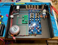
Better?
much!
btw, looking at IDC connector , connector to you , rest of pcb back - there must be "1" on left side
so , counting from left , you have pins 1+2, 3+4,5+6,7+8,9+10,11+12,13+14
pins 1+2 & 13+14 are positive leg of supply , going to common pin on front switch
then you have return wires as :
3+4 are for input 1
5+6 are for input 2
7+8 are for input 3
9+10 are for input 4
11+12 are for input 5
say that you're using 6 position switch ,leave pin 1 free (for mute position) , then pin 2 goes for input 1 wire(s) etc.
if you want lighthouse on front , you can steal positive ones from switch , route negative common from , say , relay 5 (nearest to IDC), but include series resistor there ; for 12V relays/voltage say that 12-15K is OK; for 24V relays/voltage use 25-27K ; quarter watt is Jumbo good
Last edited:
Thanks ZM!
I've been making a plinth for the SP-10MK2... so a tad off my Iron game at the moment!
I've been making a plinth for the SP-10MK2... so a tad off my Iron game at the moment!
Better?
What transformer did you use? I'm planning on Antek, as usual. My board almost done.
Russellc
What transformer did you use? I'm planning on Antek, as usual. My board almost done.
Russellc
Hey Russellc!
I wanted to jam this into 1U and Antek didn't have anything between 25 and 50VA and the 50VA—which I have—is too tall for a 1U. I sourced one from the Netherlands that's 30VA 18X2 and is comfy in a 1U—it's not shielded though... But I'll risk it.
2x 18V toroidal transformer 30VA
Shipping wasn't bad at all.
Im probably going with 2U, so either should fit fine. Might just install board into a 3U I have, but my Wayne's 2018 line stage is in there....rather keep it running.
AS-0518 - 50VA 18V Transformer - AnTek Products Corp
Russellc
Last edited:
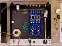
This played the sweet sweet sounds of Iron Pre tonight in test mode! No real dramas.
Took a minute to figure out perma-switching to input 1. Didn't have to touch the DC offset—born at zero! Also born at around 15.5VDC+/-....twiddled those to spec.
Took a minute to figure out perma-switching to input 1. Didn't have to touch the DC offset—born at zero! Also born at around 15.5VDC+/-....twiddled those to spec.
Attachments

.... No real dramas.
......
sounds boring........ no troubleshooting

This played the sweet sweet sounds of Iron Pre tonight in test mode! No real dramas.
Took a minute to figure out perma-switching to input 1. Didn't have to touch the DC offset—born at zero! Also born at around 15.5VDC+/-....twiddled those to spec.

Fantastic!
- Home
- Amplifiers
- Pass Labs
- What's wrong with the kiss, boy?