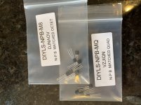
to repeat - small heatsinks just on BD transistors , no need to put them on mosfets
ZM—
Is it "bad" to have sinks on mosfets? I wasn't sure...So erred on installing them.
oh , yeah
they can catch cold
or - would you like me more if I prescribed burning 20W there , without any need
I bet , it'll be more Kosher

they can catch cold

or - would you like me more if I prescribed burning 20W there , without any need
I bet , it'll be more Kosher

Well, I may try cinemag, just went to Jenson site, and while a search brings up the part, doesn't appear to allow access to it. I will try to call. I have one set on hand already,but would like a spare for another project.
Maybe it's just because it's out of stock?
Russellc
Maybe it's just because it's out of stock?
Russellc
Sorry if I missed this earlier in the thread.
ZM,
I have the 2016 board. What selector and pot would you recommend? I think Jim mentioned two types selectors. Are both usable ?
ZM,
I have the 2016 board. What selector and pot would you recommend? I think Jim mentioned two types selectors. Are both usable ?
regarding older ( non-final) pcbs , itsallinmyhead is having all info , simply because he already made them
in all cases Lorlin switch , shorting (make before break) , 2 sections -6 positions - that's what you need and want
it can be some other brand than Lorlin , but I made pcbs for them (footprint) , and final is having input showing LEDs implemented
so , for pcb - through hole ( no solder lugs) , example : CK1030 Lorlin | Mouser Europe
pot ........ dunno - pick your own poison .......... just don't waste too much
blue ALPS is good enough ..... and certainly not the only one
if you're going to pay more, substantially - waste of the money , if you ask me
all of them are inferior to proper AVC ........ so - if you insist of making it better - instead of (any of named 3 types of ) autoformer , buy 200$ Slagle set and convert it to Poor Man Iron Pumpkin , tossing resistive attenuator completely out of story
I did explain procedure in Iron Pumpkin thread(s) , will repeat , if needed
Last edited:
Thanks for the quick reply ZM.
I already have Jensens. I will review the other thread for learning.
Alps worked well on whammy. So I'll probably do that.
I already have Jensens. I will review the other thread for learning.
Alps worked well on whammy. So I'll probably do that.
I got jensen transformers from
Jensen Transformers JT-123-FLPCH Line Output Transformer, PCB Mount
Thanks, I just ordered a spare set, much appreciated
Russellc
I messed up my build and killed the 5.1V and 27V zeners at the supply to
the relays.
Would using a shorting (make before break?) rotary switch for the input
switching have caused this? (I may have picked up the wrong switch type)
It's quite possible I've messed up the wiring elsewhere as well. If anyone
can post some pics for the wiring at the switch and at the pcb, I would be
most grateful.
Thanks,
Dennis
I messed up my build and killed the 5.1V and 27V zeners at the supply to
the relays.
Would using a shorting (make before break?) rotary switch for the input
switching have caused this? (I may have picked up the wrong switch type)
It's quite possible I've messed up the wiring elsewhere as well. If anyone
can post some pics for the wiring at the switch and at the pcb, I would be
most grateful.
Thanks,
Dennis
Although I haven't got there yet, I sure it will be very useful for me as well!😀
Russellc
switch is having nothing with these troubles ; it must be make before brake , to avoid clicksandpops while changing inputs
even if you make dead short on all IDC connector pins ( leading to selector switch) , result could be only all inputs engaged
I can't tell anything if I don't know which iteration of pcbs you guys have, so - pictures and words, please
one thing is important - each channel must use one separate section of selector switch
Sorry....won't be back home for a few days. Will ask more reasonable questions with pics then.
Thanks for the answer on the switch.
Cheers,
Dennis
Thanks for the answer on the switch.
Cheers,
Dennis
- Home
- Amplifiers
- Pass Labs
- What's wrong with the kiss, boy?


