I was going to try the Mezmerize B1 but now would go for the Iron Pre if that will be available in the diystore. If fact would even go straight for the balanced version!
Nicely reported impressions.
What output devices are you using with the Babelfish J2?
Thanks nash
My pleasure. Thank you. Subjective impressions are challenging with all the variables in a system. However, I can say with a certain amount of confidence that this is one of the best sounding combos I've had in my system. It strikes a balance that works really, really well. Some other folks came by last night for other reasons, but one guy is a solid amateur musician. He's already asked me if I'll put a set together for him. I believe his exact words were "Why isn't this mine?!" He's been by a number of times and always loved the tunes, but he took control of the computer and started playing tunes until the ladies demanded that we rejoin the "civilized world" and leave the cave.
On to your real question - I got the full kit from ZM with all parts, so "option 1" in all the schematics. FWIW - I have not tried Schade yet. That should also change the characteristics a bit. I see it mentioned often, but I'm not completely certain what it's supposed to accomplish. I'll probably give it a shot at some point. Similarly, I did not use the Borbely option in my SissySIT if that matters for some of the comparisons / opinions.
Edited to add after looking at the schematic again - Apologies, I was thinking of a different schematic. Short answer - IRFP150s.
😀
Last edited:
ZM!
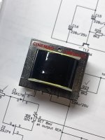
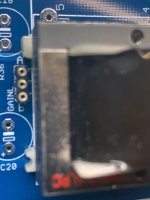
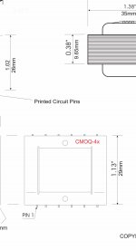
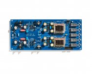
Some confirmation needed (for me) on the Cinemag install. They really seem to fit in only 1 way. All 4 outer pins are cut—they aren't connected to anything—and don't fit the PCB (as previously discussed in this thread).
See pics.
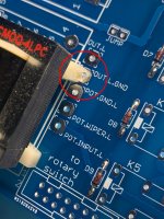
The schematic shows "pin 1", now removed, as closer to it's adjacent pin than the spacing of all of the others—yet that relationship on the actual transformer in hand is the opposite of what's in the Cinemag diagram (looking at the text orientation on the top of the transfo as a reference pin 1 should be bottom left, yet actual transformer has that relationship top right)—basically the diagram from Cinemag seems opposite of the actual transformer when looking at the pin 1 designation.
Hopefully my confusion is clear.
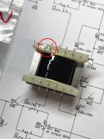
Is the cutout on the plastic support bar (red circle) just a coincidence? (Making clearance for OUT.L.GND).
This is a ton of fun so far. Thank you!
Some confirmation needed (for me) on the Cinemag install. They really seem to fit in only 1 way. All 4 outer pins are cut—they aren't connected to anything—and don't fit the PCB (as previously discussed in this thread).
See pics.
The schematic shows "pin 1", now removed, as closer to it's adjacent pin than the spacing of all of the others—yet that relationship on the actual transformer in hand is the opposite of what's in the Cinemag diagram (looking at the text orientation on the top of the transfo as a reference pin 1 should be bottom left, yet actual transformer has that relationship top right)—basically the diagram from Cinemag seems opposite of the actual transformer when looking at the pin 1 designation.
Hopefully my confusion is clear.
Is the cutout on the plastic support bar (red circle) just a coincidence? (Making clearance for OUT.L.GND).
This is a ton of fun so far. Thank you!
Attachments
yup , only one way of installing it , even if in case that you rotate it for 180deg , no biggie , result is same ........ not counting what's preferred way when thinking of winding capacitances vs. input phasing
not enough place is , certainly , my bad , but I believe I did manage these details in last/final/golden/bestthanmanafromheaven iteration of pcbs
so , just be creative , squeezing in what's needed ; result maybe little awkward to eye , but nevertheless sexy whispering in ears

not enough place is , certainly , my bad , but I believe I did manage these details in last/final/golden/bestthanmanafromheaven iteration of pcbs
so , just be creative , squeezing in what's needed ; result maybe little awkward to eye , but nevertheless sexy whispering in ears
should I say that is my wit ........ or that is coincidence ?
Haha! we KNOW there is NO difference.
Choky ZM,
I'm going to be building this soon thanks to the kindness of Jim and and Patrick. Your design is going to solve my need for 5 channels of 6 or 12 dB gain, and I will have a jumper to choose! Elegant and Perfect! 5 channels of fixed gain. Shall I have "5 Iron" on the faceplate?
My plan is to leave off all the relay switching parts, and I also won't be using volume pots.
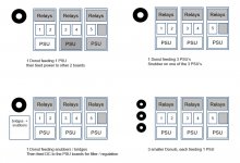
What's your opinion on best way to implement power supply for 3 boards? I have a few ideas attached, and I'm looking for your advice.
I'm going to be building this soon thanks to the kindness of Jim and and Patrick. Your design is going to solve my need for 5 channels of 6 or 12 dB gain, and I will have a jumper to choose! Elegant and Perfect! 5 channels of fixed gain. Shall I have "5 Iron" on the faceplate?
My plan is to leave off all the relay switching parts, and I also won't be using volume pots.
What's your opinion on best way to implement power supply for 3 boards? I have a few ideas attached, and I'm looking for your advice.
Attachments
you can call it Elmer Working on the Railroad , if you wish ........ 🙂
considering that GND is shared between all of these , use one Donut feeding all of them
leave intact arrangement on pcb - build all regs
parts are cheap and there are still limited number of them , so why not having it made properly
to repeat - small heatsinks just on BD transistors , no need to put them on mosfets
btw. tnx to kindness of Jim and Patrick , all interested parties are going to build them right away , so no need to introduce it in Store
well made ( static shield , magnetic shield) 30VA , 30Vct Donut is good for job
Oh, wait a sec. If these are not going to be sold through "store", I know I'd like to order a board. Need to have balanced outputs, though. Recommendation?
as usual , that's just me - stirring the Pot
as I'm informed , and there is no reason to doubt - they'll be in Store , in various levels of complexity
Boyz are having plate full , so some patience is necessary ......
as I'm informed , and there is no reason to doubt - they'll be in Store , in various levels of complexity
Boyz are having plate full , so some patience is necessary ......
Oh well. I just PM'd Jim in regard. One of these days soon it will be available.
Sorry if I jumped the gun Jim!
Russellc
Sorry if I jumped the gun Jim!
Russellc

We’ve got a small handful of beta testers and will all be taking photos and documenting the builds, looking for gotchas and understanding how to build and make it the best for all builders.
The circuit sounds incredible, this one is worth waiting for.
If you want to get a jump start on the project, order your transformers now. All three suppliers make to order and there’s a wait.
The circuit sounds incredible, this one is worth waiting for.
If you want to get a jump start on the project, order your transformers now.
All three suppliers make to order and there’s a wait.^^^ What he said! I was an impatient "Greedy Boy". So, I got a couple F6 board sets and stole the Jensens. Jensen should have them in stock now (I believe). So, if you want that brand, grab 'em now. 😀
Cinemags were pretty fast—couple of weeks—but totally depends on the workload—David definitely recommended the L version—low nickel—once he knew what the project was—He talked about "warmer" audio signal with digital sources. Very interesting. I'm not a "believer" necessarily—just reporting to the Boyz.
- Home
- Amplifiers
- Pass Labs
- What's wrong with the kiss, boy?