Thank you ZM, that is illuminating.
I will try and take some measurements and see what I end up with.
Thanks again,
just analyze resulting inductance and load which driving stage sees, and there is your answer
I will try and take some measurements and see what I end up with.
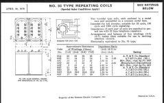
Oh no, more reading for me to figure out why this is.... I've never quite understood how transformer primary Z is determined. Sadly the specs for my repeat coil aren't too clear (93A, attached)each winding is nominally 150R
wakoo xformer logic
Thanks again,
Attachments
Sort of, not sure how much I trust my cheap LCR meter but here goes.
Coil 1 (Left Channel)
Connecting as autoformer (2-7):
Coil 2 (Right Channel)
Connecting as autoformer (2-7):
Sorry for so many figures, definitely take the inductance readings with a grain of salt.
To your point above(? or if I somehow wired things up wrong), it's interesting that measuring across 2 series windings (on each side of the xfmer) doubles the individual readings.
And measuring across both sides (4 windings) quadruples the individual values.
I don't understand transformers at all... More to read and think about!
Coil 1 (Left Channel)
| Winding Connection | Inductance | Resistance |
| 1-2 (primary, winding #1) | 0.69H | 18.8R |
| 5-6 (primary, winding #2) | 0.65H | 18.7R |
| 3-4 (secondary, winding #1) | 0.69H | 21.5R |
| 7-8 (secondary, winding #2) | 0.65H | 21.5R |
Connecting as autoformer (2-7):
| Winding Connection | Inductance | Resistance |
| 2-5 (Full primary, series connection) | 2.6H | 37.4R |
| 4-7 (Full secondary, series) | 2.6H | 42.9R |
| 4-5 (Across Full primary + Secondary) | 10.64H | 80.2R |
Coil 2 (Right Channel)
| Winding Connection | Inductance | Resistance |
| 1-2 (primary, winding #1) | 0.70H | 19.8R |
| 5-6 (primary, #2) | 0.66H | 21.5R |
| 3-4 (secondary, #1) | 0.70H | 18.9R |
| 7-8 (secondary, #2) | 0.66H | 23.5R |
Connecting as autoformer (2-7):
| Winding Connection | Inductance | Resistance |
| 2-5 (Full primary, series connection) | 2.5H | 37.1R |
| 4-7 (Full secondary, series) | 2.5H | 44.5R |
| 4-5 (Across Full primary + Secondary) | 10.4H | 80.5R |
Sorry for so many figures, definitely take the inductance readings with a grain of salt.
To your point above(? or if I somehow wired things up wrong), it's interesting that measuring across 2 series windings (on each side of the xfmer) doubles the individual readings.
And measuring across both sides (4 windings) quadruples the individual values.
I don't understand transformers at all... More to read and think about!
Last edited:
just use them as autoformer - easier load to source (preceding stage)
simple as that - higher the inductance, higher minimal impedance seen by preceding stage
you have pretty much all the tricks in Iron Pre related threads (this one being just beginning)
regarding theory, plenty of info around
in layman terms and as general info (so sorta roughly speaking) impedance and inductance in xformer are going up by square of voltage ratio/number of turns
example - that's why full primary ( two sections in series) is nominally 600 Ohms, while half of it ( just one section) is 150R nominally; double the turns. 4 times impedance etc.

Thank you - I'll look through the tips and tricks thread and see what I find. Hopefully an Iron Pre SE or Iron Turtle (edit Pumpkin) will be in my future before too long as well!just use them as autoformer - easier load to source (preceding stage)
simple as that - higher the inductance, higher minimal impedance seen by preceding stage
you have pretty much all the tricks in Iron Pre related threads (this one being just beginning)
For some reason, I never considered that inductance would be the factor that's related to the square of turns ratio. Definitely need to go back and read more carefully. (And thanks for pointing out it's a rough figure).in layman terms and as general info (so sorta roughly speaking) impedance and inductance in xformer are going up by square of voltage ratio/number of turns
I’ve ordered 2 CineMag 4hpc’s, can’t wait to connect them to my XA252’s and compare with my Blowtorch Clone preamp.
Hi,
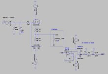
I just quickly build the buffer as below with below 0.1mA matched K389+J109, connected to the Cinemag for 12dB.
The DC-offset behind the buffer is arround 9..10mV.
I don't like trimmers, especially not in the signal path, and was thinking how to implement a DC-servo.
Below is a concept (works in LT-spice), to not connect the cinemag primary to the GND, but to the output of a DC-servo (NOT INTEGRATING, so actually a gain 1 buffer with a low pass RC).
It this a silly idea? What can I improve to have as less impact as possible soundwise?
Other options to implement a DC-servo?
Attachments
It this a silly idea?
if put against simple trimpot in sources, it is
anyhow, develop your servo circuit, build it
then build simple one, with trimpot in sources
organize listening comparison
draw your own conclusions
Again something special from mighty ZM. Soundwise very very close to my blowtorch clone, but without the heat.
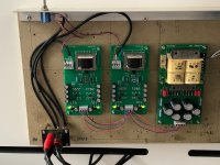
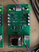
Have done a fast mock up on a planky.
Have use 2sk389bl and complement matched at idss of 10,00-10,03mA.
Regulators are Jung/Didden superreg’s with sense connections at drains of jfet’s.
🤘
Have done a fast mock up on a planky.
Have use 2sk389bl and complement matched at idss of 10,00-10,03mA.
Regulators are Jung/Didden superreg’s with sense connections at drains of jfet’s.
🤘
Attachments
what you made isn't Iron Pre - it's your own solution, evidently made with great care and pleasure

btw. I'm sure that properly driven Cinemag is better than Blowtorch


btw. I'm sure that properly driven Cinemag is better than Blowtorch
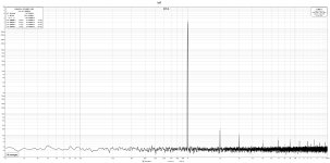
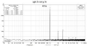
I do have some measurements that confirm thisbtw. I'm sure that properly driven Cinemag is better than Blowtorch
Attachments

- Home
- Amplifiers
- Pass Labs
- What's wrong with the kiss, boy?