In that case, can you present a summary?You should read some of the earlier discussion here on Cheever's thesis. The problem is not using test persons.
Sorry, but no. Too many years since I read it. Just do a search and find out yourself.
But since you asked for instance his claim about non-existent IMD in non-feedback amplifiers is flawed. And please remember this is only a master's thesis. There is not much scientific content outside quotes from other sources.
But since you asked for instance his claim about non-existent IMD in non-feedback amplifiers is flawed. And please remember this is only a master's thesis. There is not much scientific content outside quotes from other sources.
Last edited:

Exactly the kind of summary I expected.Sorry, but no. Too many years since I read it. Just do a search and find out yourself.
But since you asked for instance his claim about non-existent IMD in non-feedback amplifiers is flawed. And please remember this is only a master's thesis. There is not much scientific content outside quotes from other sources.
I did more than that already and the amp to be built as result won't fit any of the existing categories 😏Don't expect more if you are too lazy to do the work yourself.
Since I saw first the Sandman-Technics class AA circuits i was fascinated by this type of circuits , but I'm struggling to understand what the bootstrapped diodes do unless I'm going to deal with the opamp supply voltage around the input signal and there's very little difference even in that case with or without those diodes, while as long as the output doesn't exceed the supply there's litterally ZERO difference between having those diodes or not in the circuit.I've come up with an unusual amplifier topology involving boostrapped stuff, and that seems to have, shall we say... non-optimal clipping behavior. So it looks like I'm going to need a pre-clipping circuit.
Of course it should not distort at all until it does.
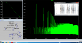
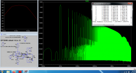
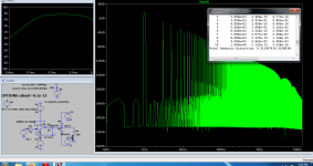
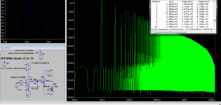
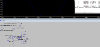
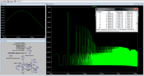
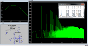
I've sketched a number of attempts, all involving bootstrapping the clipper diodes to reduce distortion by keeping voltage across them constant, which avoids nonlinear capacitance effects, leakage, etc. The bootstrap voltage is itself clipped by another pair of diodes, so when it reaches the limit, the other side of the diodes no longer follows the input signal and they begin doing their job.
The four ones on the left use diodes or transistors as diodes. They're strictly at the input of the amp, so they need an opamp buffer for the bootstrap voltage. The one on the right deletes the opamp by using the amp's output voltage (the power amp is VCVS E1) and using BJT emitter followers as diodes. Basically the two transistors' bases follow the input signal so they do nothing, until the diodes on the right conduct, at which point the transistors limit the input signal.
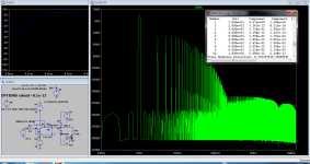
On the left is a sinewave with a smashed top.
View attachment 1071619
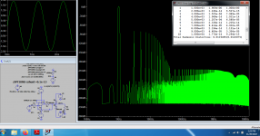
And here is THD vs input level. Simulations are sometimes slightly optimistic, but it looks like "no distortion before it has to begin clipping" is achievable.
View attachment 1071625
Thoughts?
I thought i'm going to use the smartest clipping circuit ever in my phono preamp, yet it seems this is not the One.
Attachments
-
 clipper1.png35.9 KB · Views: 97
 -
 clipper10.png40.5 KB · Views: 100
 -
 clipper9.png35.8 KB · Views: 92
 -
 clipper8.png26.2 KB · Views: 117
 -
 clipper7.png14.9 KB · Views: 125
 -
 clipper6.png33.4 KB · Views: 120
 -
 clipper5.png36 KB · Views: 103
 -
 clipper4.png40.8 KB · Views: 98
 -
 clipper3.png32.3 KB · Views: 98
 -
 clipper2.png32.4 KB · Views: 104
Hi guys! Anybody working a soft saturator at the moment?
I was thinking about using something along these lines to pre-distort (or undistort...) the bass in full-range speakers.
1) A matched pair of simple 1st-order high-pass and low-pass filters split the incoming signal.
2) The bass is passed through the saturator.
3) Bass + treble are summed.
This would obviously have to be an "active speaker", so that the volume adjustment is correctly tied to actual output levels for the speaker.
In simulations, square waves get reconstructed nicely enough, but I haven't gotten round to designing the saturator part, yet. I might implement a Raspberry Pi version (e.g.: JACK + LV2 plugins), but I haven't figured out what ADC/DAC hardware to use just yet. Another cool thing is that if I can get this up and running, I could also use high-distortion amplifiers and apply low-order pre-distortion, a la feed-forward rather than correcting by feedback.
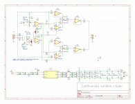
Looks very similar to this:20 years ago I did a soft clipper for a Hi Def telecine (film to video) It could
clip white vs black with independant black and white levels and a continuously
variable slope on each. This is a simplified version with continuous slope but
symmetrical pos/neg clipping. There are no discontinuities which would look
bad in video and sound like crossover distortion in audio.
The AD8036 is $12 at DigiKey. Check the data sheet as it's a very impressive chip.
https://www.analog.com/media/en/technical-documentation/data-sheets/AD8036_8037.pdf
Adding separate pos and neg clip levels with independant slope requires cascading
2 AD8036 stages but it works very well in video. Audio should be a snap.
If you attempt to build it I HIGHLY recommend using a 4 layer board with a
ground plane. The 8036 can hit 200 MHz and while stable, things get hinky on
breadboards. 5 boards would run $8 at JLCPCB.
Or you could do it with DSP in an ADAU1701.
G²
https://patents.google.com/patent/EP0586895A1/en
If this thread carries on like this it has the potentially of getting pinned on the first page👍
The digital domain offers very interesting solutions to the problem also.
Although a sample, hold and release can also be implemented in the analog domain by modifying previously mentioned Rane technique
The digital domain offers very interesting solutions to the problem also.
Although a sample, hold and release can also be implemented in the analog domain by modifying previously mentioned Rane technique
Last edited:
There are a few other topics competing for that position as well...All of them have something intersting.A digital thread should pe develloped independently cause we have already too many analogue ideeas discussed in one thread.
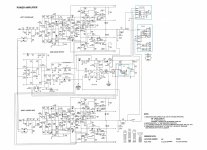
The NAD314 is a good amplifier. The only mod one would do would be to disable the class H power scheme and add an extra output device. Probably marketing and engineering were having a fun dayThere are ready, reliable.
TrueThere are a few other topics competing for that position as well...All of them have something intersting.A digital thread should pe develloped independently cause we have already too many analogue ideeas discussed in one thread.
@stratus46, I finally got the time to play with the board you sent me. It works fully as advertised of course, brilliant little circuit (attached).When this thread started, what was aked for was a soft clipper. I drew one up at the time
and posted the preliminary schematic. I now have a final version, the 4 layer with ground
plane PCB is laid out, files sent to JLCPCB, parts on the way from Digikey. That board will
be a very easy assembly. Should have test results in a couple of weeks.
There was one unexpected effect though. With the Slope pot set toward the U1A output, most of the final output signal comes from the AD8036 and is in fact the clipped signal. In such a situation, increasing the input signal hardly increases the output signal and the final output is properly limited.
Now, as you turn the Slope pot toward the output of U3B, most of the final output signal comes through the linear part of the circuit. In that situation, increasing the input signal does significantly increase the output signal too; the signal level isn't really limited.
In a situation where you want to use the soft clipper to avoid clipping a subsequent audio stage, the continued increase of the clipper output when set to soft clipping is an issue. I'm not sure at this point how to correct or circumvent it.
Jan
Attachments
@peufeu On the general topic of power amps, I would like to ask if you still recommend the enhanced LTP topologies presented here: http://peufeu.free.fr/audio/memory/memory-4-circuits.html
Your commentary on this is highly valued, having investigated the issues throughly.
Thanks,
Alex
Your commentary on this is highly valued, having investigated the issues throughly.
Thanks,
Alex
Anybody here is familiar with Bob Cordell's solution to keep the feedback loop closed even under clipping conditions, to soften the clipping?This thread is about soft clipping. Please don't hijack it.
Jan
Designing Audio Power Amplifiers, Feedback Baker Clamps, pp 367, fig 17.3. Would be interested to hear from someone who has build it.
Jan
The circuit was originally done for soft clipping HD Video and may make more sense@stratus46, I finally got the time to play with the board you sent me. It works fully as advertised of course, brilliant little circuit (attached).
There was one unexpected effect though. With the Slope pot set toward the U1A output, most of the final output signal comes from the AD8036 and is in fact the clipped signal. In such a situation, increasing the input signal hardly increases the output signal and the final output is properly limited.
Now, as you turn the Slope pot toward the output of U3B, most of the final output signal comes through the linear part of the circuit. In that situation, increasing the input signal does significantly increase the output signal too; the signal level isn't really limited.
In a situation where you want to use the soft clipper to avoid clipping a subsequent audio stage, the continued increase of the clipper output when set to soft clipping is an issue. I'm not sure at this point how to correct or circumvent it.
Jan
in that context. What you're describing is exactly what I had in mind when I did the
board and if you look closely at the pictures in post 84, that is what you see.
Adding dynamic control may work better for you.
G²
Noted. I learned things from it, so appreciate your sending me the board. I have a better idea what it is I really want, and am now doing some investigations on Bob Cordells Klever Klipper. Interesting trade-off is the level of the signal that you select as clip level, versus the threshold level of the clamp diodes.
Varying that ratio lets you trade off the onset of additional distortion with rising level against the clipping severeness. (Or, similarly, using diodes with different thresholds). The holy grail being of course no additional distortion from the clipping circuit until the very last point where clipping actually sets in.
Bob shows a curve illustrating the effect in his book (fig 17.5) and there you see appreciable additional distortion from the circuit way before clipping, but that's with a 1V signal level and a regular 0.6V diode threshold, which is about as bad as it gets.
Jan
I do have some practical experience with the feedback baker clamps that Cordell suggested in his book.Anybody here is familiar with Bob Cordell's solution to keep the feedback loop closed even under clipping conditions, to soften the clipping?
Designing Audio Power Amplifiers, Feedback Baker Clamps, pp 367, fig 17.3. Would be interested to hear from someone who has build it.
Jan
I follow the suggested schematic closely in my application.
First, this basically works well and gives very clean clipping, not soft, but very clean both into and out of clipping. The softness of clipping is just the radius of the waveform at clipping, isn't it? With the feedback baker clamps the radius is very small, but looks nice. No overshoot or overhang.
Bob writes in his book that stability of the feedback loop needs to be maintained once the feedback Baker clamps work and this is an issue in deed. I figured out that a R-C-shunt at the Q9/Q10 collector helps. In my application I have such a network at the output of the VAS, so it is somewhat obvious to compensate the clamped loop the same way.
During clipping, the clamp circuitry dumps a significant current into the feedback network into R5 and R3. Both resistors have rather low value. I could well imagine that this load lowers the OLG during clipping.
@peufeu wrote about possible pitfalls regarding TCP and feedback Baker clamps here: https://www.diyaudio.com/community/...ree-soft-clipping-circuit.388209/post-7071660
According to my practical observation so far, I could not observe instability with TPC and the clamps. Probably this is risky nonetheless and normal Miller or MIC would be a better choice when using such clamps.
Another issue is that in case the VAS output latches to either power supply rail for some reason and this may happen in case a fuse blows or ground is disconnected, transistors Q9 or Q10 likely get overloaded and fail. I experienced this issue in reality. A current limited VAS and powerful transistors help to deal with this. Also don't forget to clamp the voltage across the feedback DC capacitor.
I find the Vbe multipliers unnecessarily complicated for generating the voltage for the clamps. A Zener diode and resistor works as well.
For amplifiers with boosted front end supplies, in order to not only avoid saturation of the amplification, but also of the OPS, an "or" function can be implemented by addition of two more diodes so that the clamp works in case either the front end power supply voltage or the OPS power supply fall below the threshold.
One possible downside is that the voltage across the clamp diodes D1 and D2 is variable and thus varies the reverse capacitance of those diodes, which may have a slight impact. I experimented with a bootstrapped scheme in simulation, but this is not trivial to get right. The problem is that the bootstrap need to come from a low impedance node and be in phase. The amplifier output would be convenient, but has enough phase shift to null the positive effect of the bootstrap at higher frequency.
- Home
- Amplifiers
- Solid State
- Wanted: distortion free soft clipping circuit