
Sorry, another brain fart: unlike good wines, my brain doesn't improve with age, and I mixed up the files.
Here is the correct one.
And yes, matching is required if you want the best performance. Randomly picked diodes would probably improve the linearity by 20dB, not the 40dB afforded by the ideal spice matching.
Multiple diodes are available, in various configuration (in European and Japanese type numbers, at least, but JEDEC types are also probably available), even in packs of eight, but I am not sure about their configuration: probably common anode or cathode.
With 4, you have more flexibility: ring mixer or FW rectifier, or two uncommitted pairs.
You can run a Monte Carlo analysis to assess the effect of mismatch on the global performance
Attachments
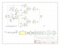
Series diode clippers have been used in AM receivers as noise limiter and as IF limiter in FM receivers. The advantage over parallel clippers is that the output doesn't exceed a set value - hard clipping.Sorry, another brain fart: unlike good wines, my brain doesn't improve with age, and I mixed up the files.
Here is the correct one.
And yes, matching is required if you want the best performance. Randomly picked diodes would probably improve the linearity by 20dB, not the 40dB afforded by the ideal spice matching.
Multiple diodes are available, in various configuration (in European and Japanese type numbers, at least, but JEDEC types are also probably available), even in packs of eight, but I am not sure about their configuration: probably common anode or cathode.
With 4, you have more flexibility: ring mixer or FW rectifier, or two uncommitted pairs.
You can run a Monte Carlo analysis to assess the effect of mismatch on the global performance
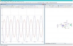
The compensation network can decrease distortion (fiddle with the value of R6, 6k8 to see the effect) before hard clipping occurs and the better that's done, the more the result resembles that of a rail to rail opamp clipper. Example in the pics, diodes at inverting input speed up recovery (and also function as input protection for unexpected, potentially catastrophic events).
Attachments
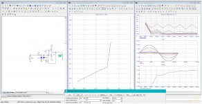
After all, mismatch doesn't have such a catastrophic effect: in this test, I sabotaged the compensating network by using different models for the diagonals, to maximize the THD:

It ended up with a 12dB penalty, not that catastrophic after all.
Some multiple diodes examples: 1N4306, 7, CA3141, µPA54H, etc.
The junctions of transistor arrays could also be used as diodes, and work better than regular diodes
It ended up with a 12dB penalty, not that catastrophic after all.
Some multiple diodes examples: 1N4306, 7, CA3141, µPA54H, etc.
The junctions of transistor arrays could also be used as diodes, and work better than regular diodes
0.01% THD, but the earlier one with magic bootstrapping simulates to 0.000000001% 
Perhaps a little bit optimistic lol
Perhaps a little bit optimistic lol
Quite right. Series diode clippers are very effective. There is less distortion with them than with parallel clippers. They work great on my amp.Series clippers are effective, and their threshold is easily configurable using resistances ratio's.
Hmmm, your amp is using parallel clippers (in a series clipper, the signal goes through the diodes when it's not clipping)
When this thread started, what was aked for was a soft clipper. I drew one up at the timeHmmm, your amp is using parallel clippers (in a series clipper, the signal goes through the diodes when it's not clipping)
and posted the preliminary schematic. I now have a final version, the 4 layer with ground
plane PCB is laid out, files sent to JLCPCB, parts on the way from Digikey. That board will
be a very easy assembly. Should have test results in a couple of weeks.
BTW it appears the ACTUAL request was for an AGC with only gain reduction. Not quite
the same as a clipper.
G²
Attachments
AGC usually has a filter in the loop to keep attenuating after a peak, like a limiter/compressor. This isn't what I want. But yeah, soft clipping is similar to an AGC without such filter, controlled only by the instantaneous amplitude of the signal...BTW it appears the ACTUAL request was for an AGC with only gain reduction. Not quite
the same as a clipper.
Best way is probably to prevent clips before they happen in the first place. Best way I know of to do that is digitally with a VST plugin such as Waves L1 or L2 lookahead limiters. They turn down the volume before a clip can occur and then recover the original gain over a time period that doesn't add excess distortion due to a too short recovery time. The current versions also protect against intersample overs. L2 adds variable, program dependent recovery time (latest L1 now has that too). With L1 manual settings, recovery times of 100ms to 1s usually sounds best. Sound is pretty transparent if only knocking off the top 3-4dB of peaks. Just need a VST host to run it, which some music player apps can do. https://www.waves.com/1lib/pdf/plugins/l1-ultramaximizer.pdf https://www.waves.com/plugins/l1-ultramaximizer
EDIT: Ideal gain recovery curve might look something like this:http://www.et.byu.edu/~ered/ME537/Notes/Ch5.pdf
EDIT: Ideal gain recovery curve might look something like this:http://www.et.byu.edu/~ered/ME537/Notes/Ch5.pdf
Last edited:
This is a simple clipper. RT1/RT2 is a trimmer, so you can adjustable the cutting point.It distort very less.

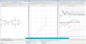
interesting circuit! It's #8 (black) on the plot.
The bootstrap circuit still wins, but it is a bit more complicated.

The bootstrap circuit still wins, but it is a bit more complicated.
Mark, which windows player supports these plugins? I'm currently using foobar..Best way is probably to prevent clips before they happen in the first place. Best way I know of to do that is digitally with a VST plugin such as Waves L1 or L2 lookahead limiters. They turn down the volume before a clip can occur and then recover the original gain over a time period that doesn't add excess distortion due to a too short recovery time. The current versions also protect against intersample overs. L2 adds variable, program dependent recovery time (latest L1 now has that too). With L1 manual settings, recovery times of 100ms to 1s usually sounds best. Sound is pretty transparent if only knocking off the top 3-4dB of peaks. Just need a VST host to run it, which some music player apps can do. https://www.waves.com/1lib/pdf/plugins/l1-ultramaximizer.pdf https://www.waves.com/plugins/l1-ultramaximizer
EDIT: Ideal gain recovery curve might look something like this:http://www.et.byu.edu/~ered/ME537/Notes/Ch5.pdf
For me at least Reply #12 suits my purpose better.
The voltage at which distortion is low (<-90dB), to the maximum clipped output voltage (max input current 20mA), is narrower.
So for a given maximum (clipped) amplitude, it gives a wider low-distortion range.
This is of course due to the sharp turn-on nature of the shunt references, compared to a diode or a BJT Vbe.
Cheers,
Patrick
OK0.2% at 1V input according tomy sim.
??
P.
For the plot in the above post, I modified R3 (using part numbers for your schematic) to 33k to make it clip at a higher voltage, around 3V, instead of 1.2V. All the other circuits use 3.2V, as a target for maximum clipped output voltage. Some distort more at lower voltages than others.
That should explain the difference.
Here's a new THD plot with R2=R3=10k, same as your schematic, but using different sim (microcap). Diode is BAS516, BJTs are BC547/557C. At 1V it's close to what you found.
I left the other circuits at their 3.2V setting, so there's no change there.
- Home
- Amplifiers
- Solid State
- Wanted: distortion free soft clipping circuit