If you clip a 200WRMS (400Wpeak) amp hard enough to fry the tweeter, I would hazard a guess that the speakers in question had the efficiency of a potato
That's Interesting. Can you please explain in more detail or point to any references?Clamping feedback doesn't work well with multipole compensation.
I didn't find anything about the "Tiger" feedback clamp implementation anywhere.
Is "clamping feedback" what Cordell refers to as "feedback Baker clamps", i.e. routing the clipped part of the signal back to the inverting input to maintain GNFB intact under clipping?
Well you can either do that or reduce the closed loop gain. If the compensation has more than one pole there's a frequency sweet spot where phase is just right to set the point where gain drops to one (ULGF) here. But below that frequency, there is too much phase shift. Lowering the gain means shifting the whole open loop gain plot down, so now it crosses unity at a lower frequency, where the phase is wrong, and it oscillates. With single pole compensation, that doesn't happen.routing the clipped part of the signal back to the inverting input to maintain GNFB intact under clipping?
Routing the clipped signal back to the inverting input means you take it from the output of the amp or the VAS, where it already has some phase shift, and inject a current in the feedback node to make the input stage believe the output is still working way below the power rails. So the input stage doesn't clip. But that stage will have some gain. If you want it to flatten and clip in the last few volts, then the feedback loop via this circuit which feeds the correction signal to the feedback node has much more gain than the amplifier itself. So it's another closed loop feedback system to make stable. And for maximum performance we already want the main feedback loop to go as high as it can, there's not much phase margin left for this extra circuit...
And when it's almost clipping, both feedback loops fight each other, and the result has to be stable XD
It's a source of endless headaches...

Thank you very much for the great explanation!
I haven't seen it this way yet. But I'm doing just that with my current amp: Combining feedback Baker clamps with two pole compensation. This is why I was asking.
On the other hand side, having some stages saturated and the compensation saturated as well, isn't going to end well, too: Ugly clipping and oscillation are for sure.
Back to your original topic: Thanks for discussing this and sharing so many great ideas. I'm enjoying this thread a lot.
Here is how I implemented it:

The main idea behind this circuit is less soft clipping, but to protect the amplifier input from gross over-voltage events like ESD, mains or loudspeaker level.
The diodes in reverse bias add some distortion due to variable capacitance, but the distortion is not too terrible.
I haven't seen it this way yet. But I'm doing just that with my current amp: Combining feedback Baker clamps with two pole compensation. This is why I was asking.
On the other hand side, having some stages saturated and the compensation saturated as well, isn't going to end well, too: Ugly clipping and oscillation are for sure.
Back to your original topic: Thanks for discussing this and sharing so many great ideas. I'm enjoying this thread a lot.
Here is how I implemented it:
The main idea behind this circuit is less soft clipping, but to protect the amplifier input from gross over-voltage events like ESD, mains or loudspeaker level.
The diodes in reverse bias add some distortion due to variable capacitance, but the distortion is not too terrible.
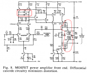
Peufeu, can you apply Bob Cordell's anti saturation clamp diode concept to the first two stages of the amp? {From his 50 watt MOSFET power amp with error correction AES paper} In effect, make the front end of the amp clip sooner than the output stage's clipping point?
Attachments
Yes:
On your schematic, the diodes on the right cleanly clip the output of the VAS, probably to avoid squeezing and saturating the transistors in the error correction stage. When that happens, the input stage will still try to drive the VAS even more, that would probably saturate one of the VAS transistors or make it misbehave in other ways. So the diodes on the left prevent this by limiting the output current of the input stage. The input stage still clips, but that's not a problem because one of the transistors will just turns off. As long as no transistor is saturated, it won't stick to the rail after clipping.
I'm working on a folded cascode:

The output from the input stage comes from the left. Q5/Q6 are folded cascodes, Q7/Q8 are superpairs to recycle base current. The diodes handle clipping before the output stage. When that happens, the input stage will pull more current. If it pulls more than I1/I2, that will reverse bias the folded cascodes Vbe and smoke them. So I can either increase the current sources (I1/I2) above the max current the input stage can provide (and waste power), or simply add Q3/Q4 which do the same thing as the diodes on the left of Cordell's schematic, and save the cascodes from reverse biasing.
However, my input stage is probably going to be an opamp, and I don't want this opamp to clip. I can't open it to put diodes inside 😉 that's why I'm considering pre-clipping the input signal.
On your schematic, the diodes on the right cleanly clip the output of the VAS, probably to avoid squeezing and saturating the transistors in the error correction stage. When that happens, the input stage will still try to drive the VAS even more, that would probably saturate one of the VAS transistors or make it misbehave in other ways. So the diodes on the left prevent this by limiting the output current of the input stage. The input stage still clips, but that's not a problem because one of the transistors will just turns off. As long as no transistor is saturated, it won't stick to the rail after clipping.
I'm working on a folded cascode:
The output from the input stage comes from the left. Q5/Q6 are folded cascodes, Q7/Q8 are superpairs to recycle base current. The diodes handle clipping before the output stage. When that happens, the input stage will pull more current. If it pulls more than I1/I2, that will reverse bias the folded cascodes Vbe and smoke them. So I can either increase the current sources (I1/I2) above the max current the input stage can provide (and waste power), or simply add Q3/Q4 which do the same thing as the diodes on the left of Cordell's schematic, and save the cascodes from reverse biasing.
However, my input stage is probably going to be an opamp, and I don't want this opamp to clip. I can't open it to put diodes inside 😉 that's why I'm considering pre-clipping the input signal.
Ha ha, no, can't do that: when the output clips, the error voltage (input of the input stage) increases, and whatever that input stage is, LTP, opamp, current feedback... it's gonna clip. If it's a LTP, one of the transistors' gonna turn off. If it's an opamp, it'll rail its output. That is problematic when coming out of clipping, because then it has to slew all the way back to normal, and that takes a while.
Series clippers are effective, and their threshold is easily configurable using resistances ratio's.

Whether it would be easy to insert in a given circuit is another story
Whether it would be easy to insert in a given circuit is another story
Sure, any raw, open-loop circuit will always have significant distortion. Compensations, feedback, error corrections can improve matters, but at a complexity cost.
I don't think a simple, uncorrected circuit can achieve a very good THD figure. Some simple, sensible measures could do better than the plain-vanilla version, but they aren't going to allow -120dB THD
I don't think a simple, uncorrected circuit can achieve a very good THD figure. Some simple, sensible measures could do better than the plain-vanilla version, but they aren't going to allow -120dB THD
This is the Spice results from post #12. "Passive", open loop.
Of course it is simulation only.
But if you look at the datasheet graphs for residual currents, I have no reason to believe it will be much worse.

And I only really need 2Vrms.
The rest are for speaker protection only, just in case.
Cheers,
Patrick
Of course it is simulation only.
But if you look at the datasheet graphs for residual currents, I have no reason to believe it will be much worse.
And I only really need 2Vrms.
The rest are for speaker protection only, just in case.
Cheers,
Patrick
The one from post 25 gives excellent simulation results, because the clamp devices are bootstrapped to the input, so their nonlinear capacitances don't get to influence the signal. I think it's simple enough. I've added a current source on the left to set the clip voltage, the two current mirrors just replicate that voltage across the two bootstrap caps for convenience. I1 could be a pot, to set it by hand, or the positive and negative thresholds could be made proportional to the current voltage on the power amp's supplies for example.Sure, any raw, open-loop circuit will always have significant distortion. Compensations, feedback, error corrections can improve matters, but at a complexity cost.
I don't think a simple, uncorrected circuit can achieve a very good THD figure. Some simple, sensible measures could do better than the plain-vanilla version, but they aren't going to allow -120dB THD
Yes, well you could use any other value, the important thing is that it matches the other two resistors labeled "clipres" so when it goes out of the allowed range, the transistors pull current through these resistors that should cancel the signal across the 1100R resistor. The value of "clipres" is defined as a little bit lower than 1100 ohms because the transistors' internal Re are in series. If the value is too high, it won't substract all the signal above the clip threshold, so clipping is soft.
This needs to be fed from a low impedance source like a buffer opamp, or a balanced receiver in the case of a power amp, otherwise whatever is in series with the 1100R resistor upstream will also count.
This needs to be fed from a low impedance source like a buffer opamp, or a balanced receiver in the case of a power amp, otherwise whatever is in series with the 1100R resistor upstream will also count.
Speakers had low efficiency and the music had a high average level - an invitation to speaker overload without hearing that. Same peak level with for instance brass instruments, no problem. The issue got me off source material using clippers and similar sound "improvement" etc.Your system was obviously mismatched to your speakers.
A common thing.
And your volume levels were unreasonable and a danger to your hearing.
But to profess to me and others that you need some sort of visual alert tells me that your careless useage with your equipment is not the equipment, but your own fault.
When using jfet as VCR, low distortion is only guaranteed when avoiding the transition not-conducting to conducting which also can be crossed by a change in Vds. So the fets have to stay "on" and there's always some loss. But such a limiter can act very fast, in a few microseconds to adapt gain which escapes being heard.But they just said it doesnt cause any distortion artifact prior to engagement. Upon engagement, it's distorting the signal, kinda by definition. Would be interesting to do a harmonic spectra for the two cases; "prior to engagement" and "upon engagement" for just the pile of input stage op-amps used to implement, say, at the 0.775V level and 0.875V.
This is mainly a result of the very low impedance level and symetrical configuration.This is what I use for 2Vrms differential input, essentially distortion free.
And passive.
Patrick
.
With low-capacitance schottky's (or diode-connected Fets) and low resistor values, any clipper will look better, including the series type
I recall the concept below from circa '68. Forensics customer wanted output of instrument to have variable threshold clipping so that he "could turn up the gain" without putting his hearing at risk. The circuit lets an a opamp clip at the rails, yet has unity gain re the input. I didn't invent the circuit--- came from a Design Idea IIRC.
Attachments
- Home
- Amplifiers
- Solid State
- Wanted: distortion free soft clipping circuit