I haven't worked through the whole design, but pos feedback issues can often be cured with a very little bit of hysteresis aound the loop.
Jan
Jan
The voltage between opamp inputs is always exactly Vout/Aol as long as it is in its linear range.@jan.didden, you are right that theory and practice deviate a lot.
In theory, the voltage across the op-amp inputs should be close to zero, in practice this is not the case at all.
That means that it increases with frequency.
Jan
I tested both variants of the clipper and like to share the results.
Here is THD vs. level for the variant with Zener diodes:

The THD measurement setup wasn't spectacular with a lot of mains frequency and other disturbance.
Not sure whether this counts as "soft" clipping.
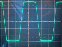
Clipping at 1kHz looks unspectacular:

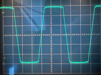
Looks still good at 20kHz:

Apparently the fast recovery diodes do a good job.
Here is THD vs. level for the variant with Zener diodes:
The THD measurement setup wasn't spectacular with a lot of mains frequency and other disturbance.
Not sure whether this counts as "soft" clipping.
Clipping at 1kHz looks unspectacular:

Looks still good at 20kHz:

Apparently the fast recovery diodes do a good job.
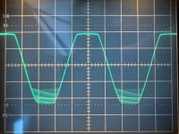
The variant with the relative clipping threshold has issues and the root cause is that I set the threshold to ~70% of the power supply voltage.
The TL072 has limited swing towards the negative rail and it shows as some kind of oscillation:

I bet this goes away with the clipping threshold set lower, like 50% of the rail voltage.
The TL072 has limited swing towards the negative rail and it shows as some kind of oscillation:

I bet this goes away with the clipping threshold set lower, like 50% of the rail voltage.
Good question - the distortion jumps more than 60dB up with just one dB more input.Not sure whether this counts as "soft" clipping.
Not really soft I would think.
One cause is that the breakdown of a zener is rather abrubt beween 0V and Vz - that abruptness (sp?) is reflected in the distortion curve.
In my experience, a circuit that uses the curve of a regular diode will be softer because that curve is much softer between 0V and Vd.
As I showed somewhere before in this thread.
Jan