Back in the 1980's we built a compressor that was quite simple and fast enough to catch the first half wave. It was similar to this:
https://www.electroschematics.com/audio-compressor-agc/
except that this is missing two important features.
1. Full wave rectification level detection. We used two NPN transistors, one common emitter and the other common base to pull down the integration capacitor. You can add a 3rd transistor so that the common base is just as sensitive and the other phase. This is the same as used to detect amp DC output in speaker protection circuits.
2. FET linearization gate signal. Half the audio signal is added to the gate control voltage so that the FET resistance remains symmetrical.
I used 2N5460s but a friend was very successful using unpowered CMOS gates. You can add pots to adjust the threshold etc., but we often just made it for instant attach and a fixed limit etc. It was similar to the classic Spectrosonic 610 compressor, but using an op-amp and P-channel FET instead of discrete transistor amplifier and an N-channel FET. The schematic for the 610 is probably on the net some place but I can't find it just now.
Here's an idea of mine, shown with opamp but applicable to any feedback amp I think
Sorry to revive an old thread, but those curves look excellent.
I'd like to implement something like this for music-creation reasons. It would sit between a device capable of +27dBU output, and an audio interface that clips at +19dBU input. All balanced. I'd probably build it into a 1U chassis for the sake of keeping things neat.
The idea would be to have it so that the interface input doesn't reach clipping, as I've observed that it's just a hard clip on that input. Not so pretty.
Questions:
- Would it be possible to implement the diode ladder passively? - It almost looks like I could just put it across the XLR +/- with a few extra resistors.
- Since the audio interface can receive 19.5Vp/p before clipping, it looks like I should try to find some lower-voltage Zeners. Are there any characteristics in particular that make them more/less suitable?
- If I wanted to add some kind of LED-based indication that the softclip was being activated, would that be easy to add to this circuit, or would it be a case of adding something else that's level-dependent and getting them to trigger simultaneously?
I'd like to get something on a breadboard asap, and guidance on the above would really help.
https://www.proaudiodesignforum.com/forum/php/viewtopic.php?p=17253#p17253
KA-Electronics Waveulator ME (Mastering Edition), which is available in board and kit form and meets some of your needs. This is may be more complex than you want, but just thought it was worth mentioning. I'm doing a modified version for my mixing/mastering efforts.
KA-Electronics Waveulator ME (Mastering Edition), which is available in board and kit form and meets some of your needs. This is may be more complex than you want, but just thought it was worth mentioning. I'm doing a modified version for my mixing/mastering efforts.
I was super-enthusiastic about the concept for a while. Looking at it from a power amplifier design perspective, the trouble I run into is that I want the best of both worlds:
Very 'clean' amplication could push the almost perfectly linear window out to ±15V, but with a sudden onset of hard clipping. I'm not sure what's better for me, TBH.
It has been a while since I've looked at an old-fashioned live scope feed of an audio signal. What many people don't seem to realise is that because the scale is linear, all you see are the peaks, and maybe the top 40dB of dynamic range. Unless it's a cheap gadget that skips frames and doesn't have any phosphor-like persistence built into the display, your eyes should not "miss" any mysterious peaks that go far above the obvious level that you can see.
For my needs, I suspect that ±2-3V should be plenty, and above that is all "overhead" and clipping. Probably more than anything, there's a kind-of internal battle, where part of me wants rolling bass, but even with something demanding like instrumental metal, most of the information is in the details between any percussive hits.
- Graceful overload for brief excursions.
- Bang-for-voltage-buck for normal levels. For instance, an approx. 16W (16V hard clipping with 8 ohm speakers) setup that can handle a 'couple' watts of bass: 1W (RMS sine wave) ~= ±4Vpk, or 4W ~= 8Vpk.
Very 'clean' amplication could push the almost perfectly linear window out to ±15V, but with a sudden onset of hard clipping. I'm not sure what's better for me, TBH.
It has been a while since I've looked at an old-fashioned live scope feed of an audio signal. What many people don't seem to realise is that because the scale is linear, all you see are the peaks, and maybe the top 40dB of dynamic range. Unless it's a cheap gadget that skips frames and doesn't have any phosphor-like persistence built into the display, your eyes should not "miss" any mysterious peaks that go far above the obvious level that you can see.
For my needs, I suspect that ±2-3V should be plenty, and above that is all "overhead" and clipping. Probably more than anything, there's a kind-of internal battle, where part of me wants rolling bass, but even with something demanding like instrumental metal, most of the information is in the details between any percussive hits.
Last edited:
Zeners clip softer than diodes used the ordinary way. They can go under 2V, but I believe you need a regular diode in series to block any forward bias. The forward drop of that diode adds to the voltage the zener will clip at.Are there any characteristics in particular that make them more/less suitable?
Check out Bob Cordell's Klever Klipper, it may just be the ticket for you.
Scroll about halfway down here: https://neurochrome.com/pages/super-gainclone-with-klever-klipper , including before-and-after distortion graphs.
It is also fully described in Bob's book.
Jan
Scroll about halfway down here: https://neurochrome.com/pages/super-gainclone-with-klever-klipper , including before-and-after distortion graphs.
It is also fully described in Bob's book.
Jan
Check out Bob Cordell's Klever Klipper, it may just be the ticket for you . . . . It is also fully described in Bob's book.
Post #6 of this thread suggests Bob's Klever Klipper and shows scope photos of its operation
Sorry Mark, missed that ...
As to a low leakage diode - did anyone mention the FDH300? I did extensive testing for my autoranger protection and selected the FDH300 as lowest leakage. The absolute value is not the lowest in the world but the leakage only starts at relatively high voltage, so when not conducting the leakage is extremely low up to 75V or so. Data sheets can be deceiving.
And of course, as mentioned several times, there is no such thing as a distortion free soft clipper.
Or maybe there is - the infinite power output amp 😎
Jan

Any diode or zener can be made to show the clipping behaviour you want. It all depends on what part of their characteristic curve you put them on, by selecting the current you drive through them and the series impedance you use. The description and design of the Klever Klipper provides a good tutorial on the matter.Zeners clip softer than diodes used the ordinary way. They can go under 2V, but I believe you need a regular diode in series to block any forward bias. The forward drop of that diode adds to the voltage the zener will clip at.
The attached is the best I came up with 20 years ago.
Jan
Attachments
Last edited:
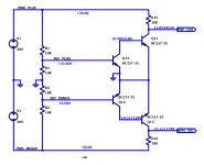
I developed a new over-voltage protection / clipper circuit that I find quite genius:

Distortion is very low because the diodes D11 and D13 have zero voltage across during normal operation because op-amp U1 mirrors the signal voltage and feeds the other side of the diodes with a copy of the signal.
This also means that the diode characteristic does not matter much (capacitance, leakage,...). High power diodes can be used without degrading the signal.
Only once the threshold is exceeded, there is voltage across the diodes.
U1 must not load the signal, else this would cause distortion. A cheap op-amp with (J)FEt input will do.
Once the threshold is exceeded, the clipping current goes through diodes D11 and D12 / D13 and D14.
Threshold is set by resistors R1 to R4.
During clipping, high frequency AC and spikes mainly go through C11 and C12 then, while low frequency / DC is handled by the transistors.
R19 may fuse during gross overload, or may be increased so that current is low enough that the resistor does not fuse.
A low value of R19 allows low noise though.
This circuit is well capable of sub-ppm distortion and can clamp currents up to 1A roughly (depends on threshold).
How do you like my circuit?
Yes, sup-PPM only below clipping.
It is not easy to design a circuit that is low distortion and clips well.
Here some simulations results:
Supply voltage = +/-10V
OP-amp: ADTL082 (LTSpice)
Diodes: 1N4007 (LTSpice) and the Schottky UPSC600 (LTSpice)
Else, as shown on schematic.
Voltage stepped 5, 6, 7, 8, 10 and 20Vp.
At 1kHz:

At 10kHz:

Conclusion:
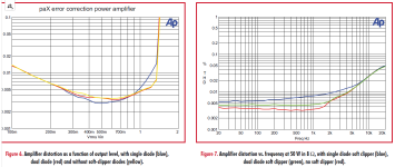
At 1kHz everything is well under control with ridiculously low distortion and nice clipping.
At 10kHz, diode recovery makes a difference. Recovery can be quite ugly with the 1N4007 model, but looks nice with the fancy SiC Schottky model.
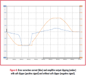
It appears as if the circuit does not behave well with voltages far beyond the power supply range (20V in this case).
With only 100R for R19, the resistor would be smoke within milli seconds though.
A higher resistance value for R19 (like 1k) would be advisable, is more common and yields better clipping, but not better recovery:

I have some PCBs and plan to built the circuit during the next few weeks using some fast recovery diodes I believe I have in my components collection.
It is not easy to design a circuit that is low distortion and clips well.
Here some simulations results:
Supply voltage = +/-10V
OP-amp: ADTL082 (LTSpice)
Diodes: 1N4007 (LTSpice) and the Schottky UPSC600 (LTSpice)
Else, as shown on schematic.
Voltage stepped 5, 6, 7, 8, 10 and 20Vp.
At 1kHz:
At 10kHz:
Conclusion:
At 1kHz everything is well under control with ridiculously low distortion and nice clipping.
At 10kHz, diode recovery makes a difference. Recovery can be quite ugly with the 1N4007 model, but looks nice with the fancy SiC Schottky model.
It appears as if the circuit does not behave well with voltages far beyond the power supply range (20V in this case).
With only 100R for R19, the resistor would be smoke within milli seconds though.
A higher resistance value for R19 (like 1k) would be advisable, is more common and yields better clipping, but not better recovery:
I have some PCBs and plan to built the circuit during the next few weeks using some fast recovery diodes I believe I have in my components collection.
I forgot to mention:
Instead of R1 - R4 and Q11 - Q14, two Zener diodes can be used to define a fixed clipping threshold, simplifying the circuit a lot.
I just like to demonstrate a solution that clips relative to the power supply voltage.
The Zener diodes would need to be high power if R19 has low resistance value.
Instead of R1 - R4 and Q11 - Q14, two Zener diodes can be used to define a fixed clipping threshold, simplifying the circuit a lot.
I just like to demonstrate a solution that clips relative to the power supply voltage.
The Zener diodes would need to be high power if R19 has low resistance value.
That's an understatement ;-)It is not easy to design a circuit that is low distortion and clips well.
The choice for diodes is indeed critical. You can minimize the recovery by minimizing the current through the diodes.
R19 can be higher for better results, 100R is quite low and as you mention, 1k should work better overall with no adverse effects on the signal before clipping.
Looking forward to your build.
Jan
It appears to me that in the circuit of post #150, transistors Q13 and Q14 operate in the reverse active mode.
- NPN Q14 has (VBE = -10V) and (VCE = -10.5V)
- PNP Q13 has (VBE = +10V) and (VCE = +10.5V)
Attachments
Like a "gain / offset" to land in the part of the curve you want. I recall reverse bias junctions ala Zener are sometimes used as noise sources. Is forward bias, as in normal diode function, inherently less noisy? Is the noise level of the Zener even something to worry about, relative to the clipping signal level?Any diode or zener can be made to show the clipping behaviour you want. It all depends on what part of their characteristic curve you put them on, by selecting the current you drive through them and the series impedance you use.
Clipping generates a spray of higher harmonics.
I'd think that it would drown the noise unless it is excessive.
Jan
I'd think that it would drown the noise unless it is excessive.
Jan
Don't some people label the anode side as positive, essentially making the schematic look upsidedown to Western eyes?It appears to me that in the circuit of post #150, transistors Q13 and Q14 operate in the reverse active mode.
This is a bit unusual for audio circuits, and I worry that transistor behavior in this mode is likely to have a much greater variance, both from unit to unit, and from low temperature to high temperature. Simulation DC bias result shown below.
- NPN Q14 has (VBE = -10V) and (VCE = -10.5V)
- PNP Q13 has (VBE = +10V) and (VCE = +10.5V)
The reverse BE bias avalanche voltage of silicon transistors is about 6V so that will be the clipping voltage. Note that LTC spice does not support the reverse BE junction behavior unless you add the parameter to the transistor model. I discovered this some time ago. It is not normally included in BJT models because using transistors this way is not common.
From the LT Spice help:
BVcbo Collector-base breakdown voltage Infin.
BVbe Base-emitter breakdown voltage Infin.
From the LT Spice help:
BVcbo Collector-base breakdown voltage Infin.
BVbe Base-emitter breakdown voltage Infin.
Last edited:
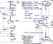
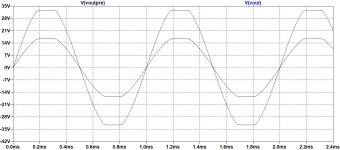
Simple soft clipping circuit. Preamp output should be high impedance.
D9 and D10 connected to bi activated.
OPS never go to clipping.
D9 and D10 connected to bi activated.
OPS never go to clipping.
Attachments

- Home
- Amplifiers
- Solid State
- Wanted: distortion free soft clipping circuit