I've come up with an unusual amplifier topology involving boostrapped stuff, and that seems to have, shall we say... non-optimal clipping behavior. So it looks like I'm going to need a pre-clipping circuit.
Of course it should not distort at all until it does.
I've sketched a number of attempts, all involving bootstrapping the clipper diodes to reduce distortion by keeping voltage across them constant, which avoids nonlinear capacitance effects, leakage, etc. The bootstrap voltage is itself clipped by another pair of diodes, so when it reaches the limit, the other side of the diodes no longer follows the input signal and they begin doing their job.
The four ones on the left use diodes or transistors as diodes. They're strictly at the input of the amp, so they need an opamp buffer for the bootstrap voltage. The one on the right deletes the opamp by using the amp's output voltage (the power amp is VCVS E1) and using BJT emitter followers as diodes. Basically the two transistors' bases follow the input signal so they do nothing, until the diodes on the right conduct, at which point the transistors limit the input signal.
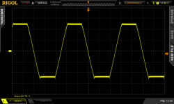
On the left is a sinewave with a smashed top.

And here is THD vs input level. Simulations are sometimes slightly optimistic, but it looks like "no distortion before it has to begin clipping" is achievable.

Thoughts?
Of course it should not distort at all until it does.
I've sketched a number of attempts, all involving bootstrapping the clipper diodes to reduce distortion by keeping voltage across them constant, which avoids nonlinear capacitance effects, leakage, etc. The bootstrap voltage is itself clipped by another pair of diodes, so when it reaches the limit, the other side of the diodes no longer follows the input signal and they begin doing their job.
The four ones on the left use diodes or transistors as diodes. They're strictly at the input of the amp, so they need an opamp buffer for the bootstrap voltage. The one on the right deletes the opamp by using the amp's output voltage (the power amp is VCVS E1) and using BJT emitter followers as diodes. Basically the two transistors' bases follow the input signal so they do nothing, until the diodes on the right conduct, at which point the transistors limit the input signal.
On the left is a sinewave with a smashed top.
And here is THD vs input level. Simulations are sometimes slightly optimistic, but it looks like "no distortion before it has to begin clipping" is achievable.
Thoughts?

Douglas Self's 5th edition of "Audio Power Amplifier Design Handbook" (C 2009) says, on page 271:
Six years later, he devotes eight pages (695-703) of the 2nd edition of his book "Small Signal Audio Design" (C 2015) to just such a thing. I guess nobody made a compelling offer (?).
Have a look at Figures 24.30 and 24.31 to see what he considers best of the best: feedforward clipping.
Some might feel that one aspect of Self's circuit might be regrettable: it is polarity inverting.
Making a clipping circuit that is wholly distortion-free below the clipping point is anything but straightforward. As I described in Chapter 2 [on p.39 --mj] , it can be done, with some non-obvious circuitry. You will, I hope, forgive me for not revealing it at the moment, but I rather hope that someone might buy the idea off me.
Six years later, he devotes eight pages (695-703) of the 2nd edition of his book "Small Signal Audio Design" (C 2015) to just such a thing. I guess nobody made a compelling offer (?).
Have a look at Figures 24.30 and 24.31 to see what he considers best of the best: feedforward clipping.
As Figure 24.31 demonstrates, this circuit is a success. There is now no measurable distortion, even just below the clipping threshold.
Some might feel that one aspect of Self's circuit might be regrettable: it is polarity inverting.
Have a look at Figures 24.30 and 24.31 to see what he considers best of the best: feedforward clipping.
Thanks for the info, but... this circuit was designed to clip hard by using feedback, which means the opamps must slew by two diode drops on each clip event, which makes a glitch. And the goal of the clipping circuit was to avoid precisely that glitch.
The tradeoff for soft clipping is increased distortion at high level, but that doesn't matter much because loudspeakers already make a ton of distortion at high level.
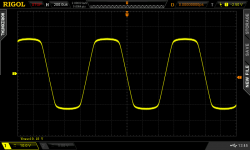
I don't like this circuit. I want the clipping to be a bit soft. When the signal isn't just one sine wave, but a bit more complex (example below) the softer clipping gives a much cleaner result.
Why even use any amplifier to the point of clipping?
Unless a person's hearing is so bad that they need the volume levels of a jet plane.
With well recorded music with a lot of dynamic range, it occasionally clips. Very occasionally.
It's mostly for aesthetic reasons.
Stepping the amplitude shows why I didn't want to put the diodes in the feedback of an opamp and force it to slew...

Also all circuit in the first post except #2, have at least 30dB less distortion at low level because they bootstrap the clipping diodes... (Self's circuit is #6 in bright green)

Also all circuit in the first post except #2, have at least 30dB less distortion at low level because they bootstrap the clipping diodes... (Self's circuit is #6 in bright green)
Hmmm, the title of this thread is: Wanted, distortion-free soft clipping circuit.The tradeoff for soft clipping is increased distortion at high level, but that doesn't matter much because loudspeakers already make a ton of distortion at high level.
I built Bob Cordell's Super Gainclone (2nd ed. D.A.P.A. p.686) with his Klever Klipper (p.521) soft clip circuit. Bob's book includes a THD plot, showing the increased distortion at high level (p.522). With soft clipping enabled, THD begins to rise when output power is ~ -3dB below the clipping point. Here are a couple of before and after pictures (vert 10V/div , horiz 200us/div); on my Gainclone the Klever Klipper is enabled/disabled by a jumper.
_
Attachments
Yes, that's a given with a soft clipping circuit.With soft clipping enabled, THD begins to rise when output power is ~ -3dB below the clipping point.
The title was a bit ironic. What matters is that distortion shouldn't increase below the level when it starts working.
But it looks like that's going to work with the 2 diode Cordell circuit also.
With well recorded music with a lot of dynamic range, it occasionally clips. Very occasionally.
Come on, you need bigger amps... speakers, and cops knocking on your door to remind you have reached the limit.
LED clipping indicators is a good starter though.
Either way it is just soft clipping so it will always add distortion.
way before the clipping characteristic is useful to prevent the amplifier from reaching hard clipping.
Using a opamp with .0002% distortion in simulation.
Using various basic circuits
distortion climbs up to .06% distortion way
before clipping is even visible.
On the threshold it climbs to .3 distortion.
when it soft clips, basically who cares at that point.
Then again I was fascinated by soft clipping, when I was using it
for intentional purposes.
So will still admit it is rather fun playing with the circuits.
Thinking back, would have saved a lot of time using simulation , since I did not
use simulation back then. But had Oscilloscope and FFT
I only used clipping in speech processors for ham & CB radio ops at work (circuits were published and worked well). For music the IM (for my ears) from any clipper is unbearable. My preference when being faced with clipping occurrences would be to design a limiter. Such a limiter only comes in action to prevent clipping and only then could produce some distortion but far less than clipping, whether hard or soft.
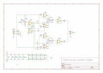
20 years ago I did a soft clipper for a Hi Def telecine (film to video) It could
clip white vs black with independant black and white levels and a continuously
variable slope on each. This is a simplified version with continuous slope but
symmetrical pos/neg clipping. There are no discontinuities which would look
bad in video and sound like crossover distortion in audio.
The AD8036 is $12 at DigiKey. Check the data sheet as it's a very impressive chip.
https://www.analog.com/media/en/technical-documentation/data-sheets/AD8036_8037.pdf
Adding separate pos and neg clip levels with independant slope requires cascading
2 AD8036 stages but it works very well in video. Audio should be a snap.
If you attempt to build it I HIGHLY recommend using a 4 layer board with a
ground plane. The 8036 can hit 200 MHz and while stable, things get hinky on
breadboards. 5 boards would run $8 at JLCPCB.
Or you could do it with DSP in an ADAU1701.
G²
Attachments
I did various sims and it looks like the choice of the diode is crucial... But is that because of model inaccuracies, I don't know. So far, BAS516 wins due to low capacitance, low leakage, and quick recovery.Using various basic circuits
distortion climbs up to .06% distortion way
before clipping is even visible.
A limiter reduces gain above a threshold, that's not different from what a soft clipper does (in fact, it's very much the same)...Such a limiter only comes in action to prevent clipping and only then could produce some distortion but far less than clipping, whether hard or soft.
Yeah it would be awesome in a scope frontend, to avoid wacky settling after the trace comes off screen and clips the input amp... But its THD is too high at audio frequencies.The AD8036 is $12 at DigiKey. Check the data sheet as it's a very impressive chip.
Unfortunately that doesn't work: to get the peaks you have to oversample a lot, otherwise there will be intersample overs.Or you could do it with DSP in an ADAU1701.
I think I'm gonna end up with something simple like that.This is what I use for 2Vrms differential input, essentially distortion free.
And passive.
In fact starting with a higher level signal would make it easier, because the clipping zone is set by the threshold of the diode. So on a 10V signal, there is much more distortion-free range than on a 2V signal. And higher levels increase noise immunity in the cables.
I like low-gain amps anyway.
I think I found a way to fix the clipping behavior of the amp, though. That would be a more "correct" way to do it lol.
PS: simulated BAS516 gives much better post-clipping recovery than BAS45 in your sim.
I think it will measure much better than you think so I will build one and see/hear.
Should take about a month so I'll let you know.
G²
Should take about a month so I'll let you know.
G²
I also think you're mistaken on the DSP. Those peaks won't make itI did various sims and it looks like the choice of the diode is crucial... But is that because of model inaccuracies, I don't know. So far, BAS516 wins due to low capacitance, low leakage, and quick recovery.
A limiter reduces gain above a threshold, that's not different from what a soft clipper does (in fact, it's very much the same)...
Yeah it would be awesome in a scope frontend, to avoid wacky settling after the trace comes off screen and clips the input amp... But its THD is too high at audio frequencies.
Unfortunately that doesn't work: to get the peaks you have to oversample a lot, otherwise there will be intersample overs.
I think I'm gonna end up with something simple like that.
In fact starting with a higher level signal would make it easier, because the clipping zone is set by the threshold of the diode. So on a 10V signal, there is much more distortion-free range than on a 2V signal. And higher levels increase noise immunity in the cables.
I like low-gain amps anyway.
I think I found a way to fix the clipping behavior of the amp, though. That would be a more "correct" way to do it lol.
PS: simulated BAS516 gives much better post-clipping recovery than BAS45 in your sim.
past the input filter. That I should be able to try on the evaluation board.
Maybe I'll put them both on the same board.
G²
"simulated BAS516 gives much better post-clipping recovery than BAS45 in your sim."
BAS45 was chosen for lowest leakage current.
Patrick
BAS45 was chosen for lowest leakage current.
Patrick
I've been chewing on getting a Rane MA-6. Supposedly, it's "the loudest 100W / ch amplifier" many have ever heard. Not that I'd need its capability for anything I'd do these days...
"USING THE BUILT-IN LIMITERS The built-in limiters in the MA 6 allow a significant increase in usable volume levels without clipping The limiters DO NOT effect dynamic response, distortion (italics mine...) or noise level of any material below about 90 watts output level. They simply “watch” the input level of each channel, and whenever the input tries to go beyond .775V, (which is the input level required for 100 watts output power), the limiter ‘jumps in’ (out of hiding as it were) and literally turns down the input level to prevent clipping. It does this very quickly (in about 1/100th of a second) so that only the peaks of the music are affected. What this means is that when ever a yellow LED flashes, a musical peak has been quickly turned down to avoid clipping. This allows you to run the amplifier at a higher continuous level, typically about 4dB SPL higher than without a limiter. And that 4dB of increased SPL is the equivalent of a 250 watt amplifier without a limiter."
The service manual is easy to find, via google "rane ma-6 service". In there you can see the active limiter component, with a box drawn around it that says "remove to defeat limiter".
I would wager the people at Rane know what they're doing. According to them, their circuit effect has some notoriety in the sound reinforcement world.
The only other bit of knowledge I can offer is that Zener diodes clip softer than regular diodes, when used in the Zener direction in an op-amp feedback.
Awesome!I think it will measure much better than you think so I will build one and see/hear.
Should take about a month so I'll let you know.
G²
I've come up with another scheme, drawing inspiration from Self: substract an inverted copy of the signal, only if it is above the clipping value. I did not put the diodes in the feedback loops of the opamps, to avoid slewing effects. Two versions: one where the diodes are bootstrapped, for lowest THD before clipping (red), and one where they are not (green).
The latter (green) is quite simple, it needs a dual opamp to invert the signal and add offset. It is only in the signal path when clipping, so it can be very cheap. Estimated THD before clipping -128dB, which is fine.
I'm gonna try current sources now.
Yes, I have been hunting for a low leakage fast recovery diode. The lowest leakage ones have very long recovery times, there's probably a compromise between the two in the manufacturing process. I picked BAS516 as a compromise."simulated BAS516 gives much better post-clipping recovery than BAS45 in your sim."
BAS45 was chosen for lowest leakage current.
Patrick
OK, it's a voltage controlled amplifier whose gain is lowered if the signal level exceeds the limit.The service manual is easy to find, via google "rane ma-6 service". In there you can see the active limiter component, with a box drawn around it that says "remove to defeat limiter".
It's difficult to make a low distortion VCA so I wasn't considering this solution...
- Home
- Amplifiers
- Solid State
- Wanted: distortion free soft clipping circuit