^ Exactly

For those with that particular need, I find ferrules like those linked below VERY useful. In addition, for those that want to take it a step further, a tiny piece of heatshrink tubing to keep the multiple ends all lined up properly post-twisting, pre-crimping is wonderful. I have not found the "dual" ferrules in an assortment. I only purchased the size I needed after using a handy dandy chart to convert "X" pieces of "Y" AWG wire is equivalent in working outer diameter to a single "Z" AWG wire.
Dual Bootlace Ferrules
Edited to fix (yet another) error in my posted link. I need to triple check these or use 'preview'.
two ... or even more...An underappreciated feature of ferrules is that you can shove and crimp two stranded wires into one ferrule.
For those with that particular need, I find ferrules like those linked below VERY useful. In addition, for those that want to take it a step further, a tiny piece of heatshrink tubing to keep the multiple ends all lined up properly post-twisting, pre-crimping is wonderful. I have not found the "dual" ferrules in an assortment. I only purchased the size I needed after using a handy dandy chart to convert "X" pieces of "Y" AWG wire is equivalent in working outer diameter to a single "Z" AWG wire.
Dual Bootlace Ferrules
Edited to fix (yet another) error in my posted link. I need to triple check these or use 'preview'.
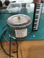
i’ve bought transformers to prepare my build, its output 18-0 x2 with 10A each, so 360VA in total.
I know Mark suggested to use 300VA 18-0x2 Antek 3218 and I’ve seen others using 4218 (bigger ampere).
I checked the dimension of Antek 3218 that is 12.5cm D and 7.9 H. But mine is 10.5D and 6.5 H
Will this works?
Thanks!
I know Mark suggested to use 300VA 18-0x2 Antek 3218 and I’ve seen others using 4218 (bigger ampere).
I checked the dimension of Antek 3218 that is 12.5cm D and 7.9 H. But mine is 10.5D and 6.5 H
Will this works?
Thanks!
Attachments
So I finally have everything assembled and wired up. I have not checked voltages yet just doing a few checks.
1. I have a hum on both channels of the amplifier. Right now I have the speaker negative hooked up to GND.O on the board. I read the assembly doc and it states that sometimes people experience this and wire it up differently - thoughts on what I should be doing there? Is this hum a sign I have something wrong?
2. I still need to do the trimpot measurement / adjustment - maybe my hum issue is related to this?
3. When trying to play music on some cheap speakers I have audio one one channel but not the other - I need to check the other channel I'm guessing I don't have the input card tightened enough ( I have some nut drivers on order for this problem given how tight everything is ). The volume is also super low but that may be an issue with my pre-amp its known misbehaving.
4. The VA draw with a single channel is ~100-110VA. With both channels hooked up I get 200-220 - is that about right? I expected it would be closer to 300
Power-supply wise I'm using the W12. It only has 2 GND / common pins and both are used for vpos / vneg - is that right? I hooked the VPOS/GND to the +/GND and then VNEG/GND -> the -/GND of the other side of the board. Would I want to use the GND/common from the power supply for the negative of the speaker terminal?
Both heat sinks get approx the same temp. I don't have an easy way to measure the exact temperature but they feel about the same so I'm pretty sure things are powered as expected. I'll see if I can get my thermal camera to work for more accurate temps.
For now I'm using the Tucson input stage. I have ishikawa put together but given the cost to replace the transistors I'm starting with a cheaper one 😉 Once I get the amp behaving I'll switch to some other input stage. I have all 5 at various states - either parts on-hand or in some state of assembly. Super excited 😉
Any recommendations on commissioning? Going to go through the docs and start thumbing through the various postings I have saved. I'm still making my way through the thread - lots to go.
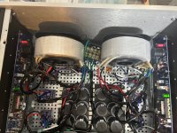
It probably depends more on the case and the power board. I'm using 2 x 200VA from antek - the depth on them is 3.9". Its a little tight but there is still room. It likely helps to mount them vertically - thats how mine are. ( I went dual 200s so a little different than the normal build )I checked the dimension of Antek 3218 that is 12.5cm D and 7.9 H. But mine is 10.5D and 6.5 H
You can see from how my layout is there is plenty of room but its kinda tight. I have the coils mounted as far to the front as I can.
Attachments

What DC voltages are you showing off the power supply banks +/- ? Should be around +/- 20-25 volts DC
So something seems offWhat DC voltages are you showing off the power supply banks +/- ? Should be around +/- 20-25 volts DC
Left channel positive reads 25. The negative reads -22
Right channel both positive and negative read 22/-22
So i guess something is off on the left channel positive - bad fet maybe? Are there voltage readings i should see at different points? I don’t recall seeing that in the threads so far but there is a lot of information to try to remember!
I have and really like the W12. It has easy access to your power output pads so you can check your power supply's unloaded output before connecting it to the amplifier board.It probably depends more on the case and the power board. I'm using 2 x 200VA from antek - the depth on them is 3.9". Its a little tight but there is still room. It likely helps to mount them vertically - thats how mine are. ( I went dual 200s so a little different than the normal build )
You can see from how my layout is there is plenty of room but its kinda tight. I have the coils mounted as far to the front as I can.
Regards,
Dan 🙂
I need some help figuring out what happened to my M2X and how to fix it. I’ll try to make this as brief as possible but it’s a long story. My M2X has been playing perfectly for 5 years. A couple of weeks ago I bought a new stand to accommodate all the pieces I’ve added over the years (eg: turntable, Iron Pre, Pearl 3, and LX-Mini crossover). All the other units worked perfectly as well. Once I completed moving everything to the new rack, the system seemed to work as expected but I had little time to really listen to it. Yesterday I sat down to listen to some records and it did not take long to realize the system did not sound right. The left channel sounded full and lively while the right channel seemed dull and lifeless. I knew something was not right. Actually it’s more accurate to say I smelled that something was not right because about that time the smell of overheating electrical parts was becoming stronger and stronger. I immediately turned off the M2X which was the source of the burning electrical smell. Upon further inspection I also found the full range speaker unit in the right LX-Mini had blown. The cone completely separated from its attachment and the little round cap in the center was blown about 2m away. I would have expected a very loud noise as the speaker self-destructed but there was none. Odd. In my past experience foolishly high volume was required to demolish as speaker. I long ago learned for the price of a tweeter to turn the pre-amp to zero before turning on new equipment or a new set-up. That appears not to have helped in this case.
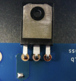
I opened up the M2X and really couldn’t see where the burning odor was coming from so I removed both amp boards. I checked the PSU and it was operating correctly. The 2.5 amp slow blow fuse was intact, and Mark Johnson’s softstart board continued to work perfectly. The amp boards were another story. The left one showed no signs of thermal abuse. On the right amp board Q1, and to a lesser extent Q2, showed signs of overheating. I also noted a small charred piece of tape that had been used to tie some of the internal cables had separated over the years perhaps aided by the recent moves of equipment. I found the scorched piece of tape sitting on the legs of Q1. In have no idea if the tape caused the problem—though I doubt it since it’s not conductive—or if it’s just another victim. It made a gooey mess on the legs of Q1. The attached photos show the effects of overheating on Q1 and Q2 on the front and back sides of the right channel board.
I have checked all the interconnects in the system to assure that they were in the right places and that none of them were shorted or making contact with circuit parts and wires. I also inspected the M2X carefully for shorts, loose wires, or additional heat abused parts. Everything appears to be as it should be. I am at a loss to explain why the amp’s right channel fried itself. My limited knowledge of circuits and experience as a user suggests three possible sources of the problem: a short, an over-voltage as for example too high a signal input voltage, or a spontaneous component failure however unlikely that may be.
I’d like to solicit your advice on 1) how to trouble shoot and fix the circuit board, and 2) how best to insure that I have eliminated the cause of the failure. Just replacing Q1 and Q2 doesn’t seem like the best thing to do since I don’t know what caused the problem. I have DVMs, a Siglent Oscilloscope, and a Siglent 3 channel/30V Lab PS available for trouble shooting. Milpitas input boards were installed during the failure; I have all of the other M2X input boards available as well. I have not included the customary pix of the amp boards because they have worked well for years and show no signs of damage or change. The system itself is working great with a replacement amp and speakers so I am pretty sure that at this point the problem resides in the amp.
Thanks for reading this long post. I look forward to hearing your thoughts about what to do next. I need a plan.
Attachments


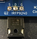
All the MOSFETS I've cooked have shorted between the Source and Drain. I'm making an unqualified assumption that you can check for shorts without removing Q1 and Q2. IMHO determining whether Q1 and or Q2 have passed away is the logical first step. I'm sure others will chime in here.
Regards,
Dan
Regards,
Dan
Last edited:
Ok, been a bit but much progress 😉
Both left and right channels read +22/-22
I debugged the tucson input stage, figured out I had read pin 1 of the soic and its not the same as pin 1 for the dip. Flipped the dip ( I had it in a socket thankfully so it was easy ).
I now have sound coming out the amplifier 😉 The right channel sounds a little softer than the left. I can't tell if its a big difference - the speakers I'm hooking up really suck!
I have a few questions:
pin 1: vneg
pin 2: signal in
pin 3: vcc
pin 4: signal out
Assuming that is the case I could hook up +24v to pin 3 and ground to pin 1. I have a bench supply but its only able to generate +/- - I can't get it to do + / - / gnd like the W12 does. If I can use my bench supply with current limiting in place I assume I could send some small voltage to the signal and see a higher ( I assume ) voltage on pin 4 - do I have that right?
I want to find a way to verify the input stages are hooked up and have at least some sense that I did it right. I had the mountain view inputs connected for just a few seconds. I touched the various transistors and found one was hot so I quickly turned things off. Guessing nothing should be hot to the touch on that board ( or any ) - I imagine they will draw only a small amount of current right?
I have the ishikawa built. I want to triple-check that I put the n and p in the right spot. I left plenty of the legs and I can probably just desolder and re-validate them.
If there is a way to validate / check the input stages I have not found it in the thread yet - I'm only on page 110 or so out of like 360.
Any ideas / references / pointers?
--- edit ---
Oh, forgot to mention. I think I did this right but I got the signal on a/b side shorted and tuned each side to between 0-1.5mv or so - is that right / good? This is using my multimeter on the speaker posts for each channel
Both left and right channels read +22/-22
I debugged the tucson input stage, figured out I had read pin 1 of the soic and its not the same as pin 1 for the dip. Flipped the dip ( I had it in a socket thankfully so it was easy ).
I now have sound coming out the amplifier 😉 The right channel sounds a little softer than the left. I can't tell if its a big difference - the speakers I'm hooking up really suck!
I have a few questions:
- Is it possible I did damage to the opamp with it flipped? Should I replace them? How would I tell?
- How can I go about testing the input boards without hooking them up directly to the amp?
pin 1: vneg
pin 2: signal in
pin 3: vcc
pin 4: signal out
Assuming that is the case I could hook up +24v to pin 3 and ground to pin 1. I have a bench supply but its only able to generate +/- - I can't get it to do + / - / gnd like the W12 does. If I can use my bench supply with current limiting in place I assume I could send some small voltage to the signal and see a higher ( I assume ) voltage on pin 4 - do I have that right?
I want to find a way to verify the input stages are hooked up and have at least some sense that I did it right. I had the mountain view inputs connected for just a few seconds. I touched the various transistors and found one was hot so I quickly turned things off. Guessing nothing should be hot to the touch on that board ( or any ) - I imagine they will draw only a small amount of current right?
I have the ishikawa built. I want to triple-check that I put the n and p in the right spot. I left plenty of the legs and I can probably just desolder and re-validate them.
If there is a way to validate / check the input stages I have not found it in the thread yet - I'm only on page 110 or so out of like 360.
Any ideas / references / pointers?
--- edit ---
Oh, forgot to mention. I think I did this right but I got the signal on a/b side shorted and tuned each side to between 0-1.5mv or so - is that right / good? This is using my multimeter on the speaker posts for each channel
Last edited:
I'm using the W12 as well. I like the layout and assembly was pretty easy. The resistors were a little interesting to get oriented but taped in place, soldered and then held soldering iron / pushed the resistor up with my other hand. Wash / rinse / repeat and I was done.I have and really like the W12. It has easy access to your power output pads so you can check your power supply's unloaded output before connecting it to the amplifier board.
Regards,
Dan 🙂
Measuring voltage while under load was not great because both the gnd pins get used. I ended up making a wago 3-wire with a pigtail to the dmm so I could measure each under load. But it was not too big of a deal - an extra gnd would be nice but very minor
@Audiobear
Make sure you clean, clean, clean all solder joints to remove all residues that could potentially bridge between solder pads. I use 99% isopropyl alcohol and a toothbrush (sometimes toothpicks) and clean multiple times then dry with thin lint free cloth to make sure I’m completely dry!
Make sure you clean, clean, clean all solder joints to remove all residues that could potentially bridge between solder pads. I use 99% isopropyl alcohol and a toothbrush (sometimes toothpicks) and clean multiple times then dry with thin lint free cloth to make sure I’m completely dry!
Audiobear - Looks like your power MOSFET thermal interface solution may have eventually failed. My crystal ball is very hazy and I can't see your previous mounting arrangement. For long term stability, you want:
- a proper large format washer on the component to spread the pressure evenly, I use a Hillman 3/4" diameter washer, and it's quite thick
- a springy steel split / lock washer between screw head and said large washer
- proper mounting pressure - for my output devices, I use a fixed torque T-Handle specified for 1.0 Nm
Never underestimate thermal-cycling and effects. Over time, this cycling can absolutely cause a loss of this critical / required component-to-heatsink clamping pressure.
So i left the amp powered up over night and made some fine adjustments. Each channel is approx 0-1.5mv. I can’t get it any better than that. Super fine adjustment sends the voltage out to either negative values or 10-20mvOk, been a bit but much progress 😉
Both left and right channels read +22/-22
I debugged the tucson input stage, figured out I had read pin 1 of the soic and its not the same as pin 1 for the dip. Flipped the dip ( I had it in a socket thankfully so it was easy ).
I now have sound coming out the amplifier 😉 The right channel sounds a little softer than the left. I can't tell if its a big difference - the speakers I'm hooking up really suck!
I have a few questions:
On the input stage checking. I think I'm reading things right:
- Is it possible I did damage to the opamp with it flipped? Should I replace them? How would I tell?
- How can I go about testing the input boards without hooking them up directly to the amp?
pin 1: vneg
pin 2: signal in
pin 3: vcc
pin 4: signal out
Assuming that is the case I could hook up +24v to pin 3 and ground to pin 1. I have a bench supply but its only able to generate +/- - I can't get it to do + / - / gnd like the W12 does. If I can use my bench supply with current limiting in place I assume I could send some small voltage to the signal and see a higher ( I assume ) voltage on pin 4 - do I have that right?
I want to find a way to verify the input stages are hooked up and have at least some sense that I did it right. I had the mountain view inputs connected for just a few seconds. I touched the various transistors and found one was hot so I quickly turned things off. Guessing nothing should be hot to the touch on that board ( or any ) - I imagine they will draw only a small amount of current right?
I have the ishikawa built. I want to triple-check that I put the n and p in the right spot. I left plenty of the legs and I can probably just desolder and re-validate them.
If there is a way to validate / check the input stages I have not found it in the thread yet - I'm only on page 110 or so out of like 360.
Any ideas / references / pointers?
--- edit ---
Oh, forgot to mention. I think I did this right but I got the signal on a/b side shorted and tuned each side to between 0-1.5mv or so - is that right / good? This is using my multimeter on the speaker posts for each channel
I hooked the amp up to a known good preamp and the right channel is consistently much softer/quieter than the left
I’m going to switch the input cards to see if that follows the input stage or stays with the amp board. Not sure which i prefer!
With the voltage reading in theory the channels should be very close to each other. Both are in that same voltage range
Any thoughts on what to check for?
First I would notate the AC voltage on speaker outputs with a known input voltage (i.e. tone generator of ~50mV) to see how "off" one channel is from the other. Then you need to determine is it lower in amplitude/voltage, or reduced frequency response? I have had an incorrect capacitor placed in the input section and after some debugging, and help from this forum, using a frequency generator and a tone sweep, figured out I was missing 2-3 octaves in my FR. Which made it sound 3-4 db softer on that channel.
If there is a voltage variation, next would be to track voltage from the input to the output stages. Figure out the AC voltage signal on the RCA going in (~50mV), then to the input board, should be 50mV, then out of the input board, should be higher, then to the output stage, which should match what you are seeing on the speaker outputs. I'm guessing on the voltages, because I'm not smart enough to translate that as the gain in the M2x. Moral of my suggestion - make sure there is a voltage increase in the FE to the outputs, compared to the RCA plug.
BE CAREFUL, a slip of the probe could lead to catastrophic damage to the amp.
I’ll check again and post the values but if I remember correctly there was significant resistance between the source and drain. I was looking for a short between any two legs and couldn’t find one. Warrants doing it again and stating va
@Audiobear
Make sure you clean, clean, clean all solder joints to remove all residues that could potentially bridge between solder pads. I use 99% isopropyl alcohol and a toothbrush (sometimes toothpicks) and clean multiple times then dry with thin lint free cloth to make sure I’m completely dry!
I totally agree. I use isopropyl alcohol too as you describe. The backsides of both the boards are clean. What happened at these MOSFETS I don’t know. Maybe I neglected to clean the joints on top—it looks to me like they were soldered from top but it’s so long ago that I don’t remember. FWIW the MOSFETS on the other channel are much cleaner. I had just assumed that the charred piece of tape made the mess, but maybe not. When I get back to the bench I’m going to check for shorting between the legs.
The MOSFETS were mounted on alumina ceramic pads with a light layer of Superlube Silicone Heatsink Compound. Washers were as you describe and I use a 0.9Nm torque wrench. Can I guarantee that this joint was properly torqued? I honestly don’t know. It had not occurred to me that thermo-cycling could have loosened the lock washer and nut. It’s too bad both sides are now disassembled. I don’t recall the nuts being particularly loose when I disassembled amp, but it’s possible.Audiobear - Looks like your power MOSFET thermal interface solution may have eventually failed. My crystal ball is very hazy and I can't see your previous mounting arrangement. For long term stability, you want:
- a proper large format washer on the component to spread the pressure evenly, I use a Hillman 3/4" diameter washer, and it's quite thick
- a springy steel split / lock washer between screw head and said large washer
- proper mounting pressure - for my output devices, I use a fixed torque T-Handle specified for 1.0 Nm
Never underestimate thermal-cycling and effects. Over time, this cycling can absolutely cause a loss of this critical / required component-to-heatsink clamping pressure.
The MOSTFETs clearly need to be replaced. I’ll do that first. I’ll check the components that can be checked in situ but there’s not many downstream of the transformer. I have a test rig with heatsinks and power supplies. I just may see what happens with new MOSFETs installed. What else should I check before applying voltage to the boards again?
Those pads are high performance for sure. I've been doing the Keratherm for awhile, on my stuff. Maybe verify flatness of the heatsink? No burrs at the mounting hole or FET surface, etc.
- Home
- Amplifiers
- Pass Labs
- The diyAudio First Watt M2x