I finished my M2X a few months ago.. I used a few mitigation strategies to reduce the hum.. My hum was not bad to start with, but could hear it in both of my monoblocks with my ear close to the woofer in my speakers. In order of noise dampening, I found that rotating the transformer even 10-15 deg made a HUGE difference in noise reduction. After that, the mu-metal shield was next biggest reducer.. I also used a metal can on the primary tranformer, as well as ferrite rings. The last two on the list, IMHO made the smallest difference.. @bilsch, Enjoy the read.. I took prob close to a month, 20 pages at a time, making notes along the way, lots of fun reading everyone's thoughts! Enjoy!
Bilsch,
The offset adjustment pot, RV1 is very close to the Edcor transformer, so the box needs to made from thin sheet stock to get between the two (or a notch in the cover. It really is not hard to make the box out of mu-metal if you have tin shears. I found using adhesive to adhere the cutting pattern onto the mu-metal sheet and cutting it out is not that difficult. I also found using a piece of 1x2 wood to use for bending the sides of the box against also helps.
Another tip is apply a couple layer of Kapton tape on the inside surface of the box before bending, it is a lot easier to do in then than later. You basically then use Kapton tape to hold the box together.
It took me maybe an hour for the first cover and figuring out my mistakes, and then half the time for the second. It is not hard. The mu-metal is expensive though, but get enough.
Be aware you need mirror image boxes if you use the posted cut pattern because of the tab used to screw the cover in place (has to align with the PCB mounting screw).
David

So I've seen it referenced a few times but I have not seen any points TO it. What is a bulb tester and how do I go about making one?
I have a variac. My plan was to use the variac to test the AC -> DC ( without anything hooked up ) to measure voltages. Using the Variac initially to slowly ramp up to main ac voltage levels. Checking voltages during the ramp-up.
I have most of the bits for the power supply. Waiting for resistors ( I ordered for a different ps and changed my mind so ;( ~10 worth of spare resistors for later )
I have the amp boards populated. Is there any harm in powering up with full voltage without the input stage? My plan was to do this and check voltages on the board ( amp board ) after the power supply check. ( eg do another variac slow voltage ramp-up )
Baby steps 😉 Still got lots of reading to do. Maybe by this weekend I'll be ready to hook things up. I'm going to fiddle with different layouts for the power supply, rectifiers and cl60 boards - I have some of those vertical mount plates that I'm contemplating using to make better use of the space - mount the ac side on the side facing the transformers and then route the dc to the other side with the power supply board. We'll see 😉
For the curious I'm using the W12 dual mono for power supply so 4 rectifiers and 2 ac soft-starts. Probably total overkill but hey 😉
A Variac won't save you if you don't know how to use it, but a bulb tester will catch most mistakes, automatically.
I have a variac. My plan was to use the variac to test the AC -> DC ( without anything hooked up ) to measure voltages. Using the Variac initially to slowly ramp up to main ac voltage levels. Checking voltages during the ramp-up.
I have most of the bits for the power supply. Waiting for resistors ( I ordered for a different ps and changed my mind so ;( ~10 worth of spare resistors for later )
I have the amp boards populated. Is there any harm in powering up with full voltage without the input stage? My plan was to do this and check voltages on the board ( amp board ) after the power supply check. ( eg do another variac slow voltage ramp-up )
Baby steps 😉 Still got lots of reading to do. Maybe by this weekend I'll be ready to hook things up. I'm going to fiddle with different layouts for the power supply, rectifiers and cl60 boards - I have some of those vertical mount plates that I'm contemplating using to make better use of the space - mount the ac side on the side facing the transformers and then route the dc to the other side with the power supply board. We'll see 😉
For the curious I'm using the W12 dual mono for power supply so 4 rectifiers and 2 ac soft-starts. Probably total overkill but hey 😉
It's extra reassuring when you're able to install a cheap expendable DVM as an AC ammeter (10 amp scale) in series between the Variac and the audio equipment under test. Now you can wind up the Variac very slooooooooowly while monitoring the AC current. If current starts to go abnormally high, spin the Variac knob down to Zero Volts quickly, preventing a fuse blowout or overstressing the audio gear. Just tell yourself, this is the ammeter which the Variac manufacturer should have installed, but he forgot.
If you turn up the Variac voltage slowly during bring-up and testing, there's no inrush of current, just a gradual smooth rise. So you can temporarily install a fast-blow fuse during Variac testing, protecting your gear even further.
If you turn up the Variac voltage slowly during bring-up and testing, there's no inrush of current, just a gradual smooth rise. So you can temporarily install a fast-blow fuse during Variac testing, protecting your gear even further.
DVM? Not sure I follow on that.It's extra reassuring when you're able to install a cheap expendable DVM as an AC ammeter (10 amp scale) in series between the Variac and the audio equipment under test.
My variac has an analog current meter - not sure how much I trust it but I can monitor it during the ramp-up easily enough. I have another amp that I can hook the variac up to and I know its current draw - have a killawatt too so 😉 Options!
I just plug my DBT and variac combination into a Kill-A-Watt type meter with a digital amperage reading.
Dan
Dan
Bilsch,
Wire a lightbulb in series as a current limiter like this.
https://www4.picturepush.com/photo/a/10715222/1024/Anonymous/AmpCurrentLimiter1.jpg
This is the lowest form of life. It lacks a fuse and it is quite flimsy and useless unless it is combined with a variac so that is the lamp gets too 'lively' you can turn the voltage back and check your work.
What a great tip 😀It's extra reassuring when you're able to install a cheap expendable DVM as an AC ammeter (10 amp scale) in series between the Variac and the audio equipment under test. Now you can wind up the Variac very slooooooooowly while monitoring the AC current. If current starts to go abnormally high, spin the Variac knob down to Zero Volts quickly, preventing a fuse blowout or overstressing the audio gear. Just tell yourself, this is the ammeter which the Variac manufacturer should have installed, but he forgot.
If you turn up the Variac voltage slowly during bring-up and testing, there's no inrush of current, just a gradual smooth rise. So you can temporarily install a fast-blow fuse during Variac testing, protecting your gear even further.
Like these?
https://www.mouser.ca/c/circuit-protection/fuse-holders/fuse-holder/?fuse size / group=5 mm x 20 mm&mounting style=Panel Mount&product=Fuse Holders&type=Panel Mount~~Rear Mount&instock=y&sort=pricing&rp=circuit-protection/fuse-holders/fuse-holder|~Type
I am confused. The fuses that you referenced are panel mount.
Hello bilsch,
I often use the 5x20mm fuse holders from Schurter or Püschl or ESKA:
https://www.reichelt.de/de/de/shop/...-250-v-10-a-schwarz-sch-31010015-p243285.html
Cheers
Dirk
I often use the 5x20mm fuse holders from Schurter or Püschl or ESKA:
https://www.reichelt.de/de/de/shop/...-250-v-10-a-schwarz-sch-31010015-p243285.html
Cheers
Dirk
yea the fuse mount I referenced was panel mount - not what I wanted ( hence the "guess I could 3d print a thing" bit ). This is what I ended up getting: https://www.digikey.com/en/products/detail/schurter-inc/0031-5001/640403
Thanks @Ben Mah and @cubicincher !
Thanks @Ben Mah and @cubicincher !
Progress 😉 Waiting on some crimp connectors so I can wire up the rectifiers.
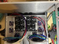
I'll probably go with this layout - any concerns having the rectifiers near the amplifier boards? Should I move them back by the coils - its a little tight in there but I could probably make it work - put the rectifiers in-between the filter board and the coil on either side.
Question on the toroid. Is it worth getting a toroid cover for each or just have them as I have them?
Attachments
I would suggest drilling out the snubber board hole so the bolt head passes through to the rectifier base, not applying load to the PCB. I made magic smoke come out on a couple fuses when the the snubber board shorted to the metal rectifier case through the solder mask.
my answer is try it without then try it with. find out for yourself if worth it.
Oh I'm going nuclear on the rectifiers - nylon screw, nylon standoff and ... yep nylon nut 😉 No shorting for me. I saw the post on the shorted rectifier and do not intend to repeat that one!I would suggest drilling out the snubber board hole so the bolt head passes through to the rectifier base, not applying load to the PCB. I made magic smoke come out on a couple fuses when the the snubber board shorted to the metal rectifier case through the solder mask.
I'll check on the diameter of the screw head and see if I can drill that out - good idea! To be honest though, I can go fairly light on the tension and just use my soldering iron to melt the nylon so it never loosens!
Also of interest? Because I'm spreading my AC out across 4 freaking rectifiers the current load on each should be pretty low. Its what like 1.5 amps total spread by 4? These things should be cool to the touch!
So I'm curious I was reading https://www.diyaudio.com/community/threads/the-diyaudio-first-watt-m2x.321925/post-5769227
How important are the various resistor types? When I did my order I was not super detailed I just found mostly matching ( I ordered 1/2 watt vs 1/4 that sort of thing ).
I have not yet powered my amp up. Is it worth going back to re-do the resistors and/or other components? The over-sized resistors won't be an issue they just look funny right? I can send a photo to show what I mean if that would help.
Maybe asked another way - is there a "tricked out" set of components I could/should use? I have matched fets on both boards. The rest is not quite as meticulous.
I also did not do the blasphemous resistor value changes as described ... elsewhere I don't have the link handy. I went with stock values for everything. Is this thought going down the rabbit hole of premature optimization or worth following?
Each rectifier will see the 1.5A if each channel has its own power supply board.
Is the case of your rectifiers plastic or metal? Shorting of the snubber board is an issue only if the rectifier case is metal. If your rectifiers have a metal case, you will need to leave a gap between the snubber board and the rectifier. The screw is not the path of the short. The reason for drilling the snubber board is to allow the screw to bear directly onto the rectifier.
Looking at your picture of post #6,915 it looks like you have the power supply boards at the front of the chassis and the power transformers at the back of the chassis. That is not good for the amplifier as the amplifier board has a signal transformer mounted toward the back of the chassis. The power transformer should be located as far as possible from the signal transformer, so the best location for the power transformers is at the front of the case.
- Home
- Amplifiers
- Pass Labs
- The diyAudio First Watt M2x