So i checked s bunch of resistors. R6 the side with low volume reads 37k but should be 47k
I tried assisting rv1 to see if that was messing with the value and it did not appear to be
On the good channel r6 reads 24.5k which is wrong too so I’m not sure what to make of this. Thoughts?
I tried assisting rv1 to see if that was messing with the value and it did not appear to be
On the good channel r6 reads 24.5k which is wrong too so I’m not sure what to make of this. Thoughts?
Got a question about dropping my voltage in my m2x to use other daughter boards.
I have a basic CRC psu with AS-3220 transformers. I have had the ishikawa in the amps for the longest time and I noticed my rail voltage is right around 29V. Is there a quick fix in replacing the .47 ohm resistors with larger ones to drop my voltage to use with all the daughter boards or am I best off changing the transformers?
I have a pair of Triad VPT - 160VA 18VAC secondaries I could use instead but think the resistor route would be easier.
You can certainly up the "R's" in the CRC, within reason. Watch the dissipation obviously. Ohm's law is your friend, run the numbers. A better way to gobble up ~4V or so is by switching to a cap-multiplier supply with MOSFETs rather than a CRC. In exchange for the "lost" voltage, you get rewarded with some super low ripple. I ran a version shared by diyA member "juma" for a long time with excellent results.
Yea. I wanted to go this route with SLB (Smooth Like Butter) boards but couldn’t find them online.
I may just go with the smaller transformers to be safe since I have them on hand
I may just go with the smaller transformers to be safe since I have them on hand
They are out of stock right now on the dual rail version. I ended up getting a couple of the single rail boards to try for other projects.
So no beeps ;( I verified the multimeter was in the right setting - if I tap the ends I get loud noisy beep sound. Between these pins its dead silent. I checked the same pins on the one where sound seems to be working ( was at least! ) and it too is silent between those pins. Are both bad? I'm not sure what I should be seeing/hearing hereWith the meter in beep (continuity) mode, are 5&7 connected?
You have both transformers removed?
Are you sure you're measuring the correct pins? Having the same problem on both points to a measurement error more than an identical dual failure. (although it's not out of the question...)
Are you sure you're measuring the correct pins? Having the same problem on both points to a measurement error more than an identical dual failure. (although it's not out of the question...)
So on a somewhat different path than my edcor journey 😉
How do you go about adjusting the pot on the ishikawas? The doc mentions the pot is optional but there is no mention of what/how to adjust. Is it purely by ear or should there be some resistance / voltage reading somewhere to calibrate this?
Also in talking with someone else they have the jfets for the ishikawa oriented back to back and shrink-wrapped together. I had intentionally made sure they were not touching - is there some reason to do something like that for the ishikawa? Easy enough to re-orient them now before I put them into the amp whenever I get to that point.
I have at this point tested both input boards for mountain view, tucson and ishikawa - sound passes through all 3 but I have not spent any significant time with any of them yet. I'm debating putting the Austin and Norwood though I think I'm missing 1 capacitor for the norwood.
Re: Ishikawa's potentiometer -
(Editors note (Jim again) You can not adjust this by ear. Get some kind of audio analysis software (ARTA, Electroacoustics Toolbox, etc...) or an old boatanchor distortion analyzer like the HP 339 series, or a spectrum analyzer, so you can actually measure and see the changes in the distortion and distortion distribution.)
Yea I am really confused on that point.You have both transformers removed?
Are you sure you're measuring the correct pins? Having the same problem on both points to a measurement error more than an identical dual failure. (although it's not out of the question...)
So at this point the working board still has the edcor attached.
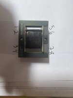
Attached is an image of what I think are the pin mappings - maybe I have the wrong mapping? There is no pinout on the edcor itself so maybe I just have it wrong?
Attachments

eek maybe I'm better off not having it? I don't have that kind of gear sadlyRe: Ishikawa's potentiometer -
So I see there is a document but its not a link / not working for me.The only pins that matter for measurement are 1,3,5,7

In https://www.diyaudio.com/community/threads/the-diyaudio-first-watt-m2x.321925/post-7932938 I see the 3 pins per side but physically each side has 4. I assume pins 1 ( outer ) and pin 3 ( right side but in one pin ). Then the same - pin 5 would be across from pin 1, pin 7 would be across from pin 3 right?
yea that I can see!
OK now that I see the proper pin mapping I had pin 5 across from pin 1 - its across from pin 4 so I was not giving logical readings sorry about that!
Ok with actual pin 5 and actual pin 7 I get no beep in continuity mode and 0L ( eg no connection/reading ) trying to measure the resistance.
With the "good" board I get continuity / beep and a reading of 234 ohm ( pins 5 to 7 again )
- Home
- Amplifiers
- Pass Labs
- The diyAudio First Watt M2x