
You have made me wonder if over time with multiple on-off cycles the nuts just backed off. Maybe that’s a good reason to never turn off your equipment but I find it hard not to do so. We’ll find out after I reassemble with new MOSFETs.
Both transistors and mounting places were lightly sanded with 600 and 1200 grit emory cloth on a flat block, cleaned well, and dried with an airstream from a can. The silicone lube is supposed to fill any remaining gaps. I think these started out ok. I can’t find the notes but I recall that the heatsinks and transistors were not very hot at all—I’m kind of thinking mid-40s to low 50s. I’ve built enough amps since then that I could be imaging those numbers...
Both transistors and mounting places were lightly sanded with 600 and 1200 grit emory cloth on a flat block, cleaned well, and dried with an airstream from a can. The silicone lube is supposed to fill any remaining gaps. I think these started out ok. I can’t find the notes but I recall that the heatsinks and transistors were not very hot at all—I’m kind of thinking mid-40s to low 50s. I’ve built enough amps since then that I could be imaging those numbers...
I agree with Darr. If it were me and I had no other guidance I would first check R13, and R14 while Q1 and Q2 were removed. If they passed inspection I would install new mosfets. After that, using my variac I would energized this channel alone while monitoring three things. I would monitor the voltage drop across R13, and R14, and have a meter on the output to pickup any potential strange DC offset. I believe Mark posted somewhere that the voltage drop across R13, R14 should be somewhere around 0.6v-0.75v?
Regards,
Dan
Regards,
Dan
This Mark's manual can help you find the error.
https://www.diyaudio.com/community/threads/the-diyaudio-first-watt-m2x.321925/post-6419568
https://www.diyaudio.com/community/threads/the-diyaudio-first-watt-m2x.321925/post-6419568

Thank You Mark 🙂I like to have everything clean after soldering. I use a lot of cleaning chemicals. Norwood passed through the SMT reflow oven. Now I have to find time to exchange and listen
Ok I think I may be onto something.
I took voltage readings all over the freaking place. I had to take the channels / power supply out of the chassis to do it - I just could not get in there any other way.
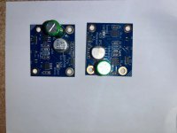
I don't know the pin mappings on the edcor. The left and right of the image below are working on the left and not working on the right. There is a big voltage difference on one of the pins between the edcors.
Thoughts? Is this looking like a bad (maybe damaged?) edcor? I'm going to take the bad board off of the heat sink tomorrow and look over the solder joints for the edcor.
I have voltage readings of each board on all resistors and the diodes. I can attach if anyone is curious but the big difference here is the edcor. I also managed to get my flir working so I have top views of the thermal - you need flir's software to get readings but it is pretty neat. I took the thermals with the edcor covers on - tomorrow I may fire it up and take again after an hour or something so the temps equalize - maybe that'll prove/show something?
I took voltage readings all over the freaking place. I had to take the channels / power supply out of the chassis to do it - I just could not get in there any other way.
I don't know the pin mappings on the edcor. The left and right of the image below are working on the left and not working on the right. There is a big voltage difference on one of the pins between the edcors.
Thoughts? Is this looking like a bad (maybe damaged?) edcor? I'm going to take the bad board off of the heat sink tomorrow and look over the solder joints for the edcor.
I have voltage readings of each board on all resistors and the diodes. I can attach if anyone is curious but the big difference here is the edcor. I also managed to get my flir working so I have top views of the thermal - you need flir's software to get readings but it is pretty neat. I took the thermals with the edcor covers on - tomorrow I may fire it up and take again after an hour or something so the temps equalize - maybe that'll prove/show something?
Attachments
I should note that all voltages were taken without any music / sound. The pre-amp was hooked up but I don't recall the volume level - I don't think that would effect much if anything on those. Maybe the readings on the input?
Could there have been "damage" to the Edcore pins from the heat required to solder it on? I know I had a little bit of plastic melting on mine and was concerned it could have done damage, but the tiny copper wire appeared to still be attached, and there were no issues with power up, bias and testing, so I lucked out. Something easy to inspect if you have access. With that said, one would expect no sound, not just quiet sound if I understand the circuit correctly (which I probably don't 😅).
Last edited:
Yea I had wondered that. The way I was doing the solder may have been too hot and I could certainly see doing damage if its really sensitive.
When I say little sound its ... pretty significant in terms of the difference. The voltage readings on the left side really don't match on the right.
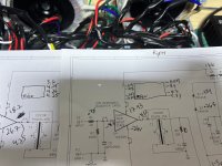
Left / right, bottom up
4.25 / 4.3 - that is close enough imo. Match
4.26 / 8.7 - wait what? Thats .. approx double from the first reading on the bad channel
4.25 / 8.4 - still approx double that seems wrong
3.6 / .005 - thats way off
Either something strange happened or maybe I just got a bad one? Could I have damaged it - yea absolutely. I understand whats going on in the edcor to make sense of that - why is it double ish on the right on those other pins and then suddenly 0 ish. That seems off.
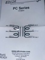
Assuming that pin maps to pin 7 on the edcor diagram below that low voltage would absolutely explain why the sound is super low on that channel imo.
Anyone able to explain / reason whats going on here?
When I say little sound its ... pretty significant in terms of the difference. The voltage readings on the left side really don't match on the right.
Left / right, bottom up
4.25 / 4.3 - that is close enough imo. Match
4.26 / 8.7 - wait what? Thats .. approx double from the first reading on the bad channel
4.25 / 8.4 - still approx double that seems wrong
3.6 / .005 - thats way off
Either something strange happened or maybe I just got a bad one? Could I have damaged it - yea absolutely. I understand whats going on in the edcor to make sense of that - why is it double ish on the right on those other pins and then suddenly 0 ish. That seems off.
Assuming that pin maps to pin 7 on the edcor diagram below that low voltage would absolutely explain why the sound is super low on that channel imo.
Anyone able to explain / reason whats going on here?

yea my usual pattern may be to blame. I tend to set the iron hot ( probably too hot )Very thin wire. Very hot iron….in/out quickly!
850 on a hakko 888d. I think thats the model - its the digital hakko 😉
But I tend to heat, then add solder, then hold there for a bit to make sure the solder has flowed and then remove. I'm guessing I damaged it ;(
Are these DC voltages? They don't make a lick of sense to me. Pin 3 goes to ground, should be zero. Pin 1 and 5 are tied together, should be the same, 7 is the output to the R5 and beyond. Measured mine and I have no DC present across pins 1,3,5,7.
So i did not look to see whether it was detecting ac or dc. It was in auto.
Each reading was with the ground attached to ground and then on each respective pin walking down the line
I’ve removed the edcor and prepped to replace. New is on order just a matter of them building/shipping.
I’m going to take some readings of the suspected bad edcor. With having removed it its no longer in the same state so the readings don’t really matter. With the high heat used to solder and desolder I probably damaged it when i initially installed it.
When i solder it again it’ll be with 650 temps and with flux. I practiced with another board. It’s messier but it worked
- Home
- Amplifiers
- Pass Labs
- The diyAudio First Watt M2x