Yea the base of the rectifier is metal - its why I'm planning to use the nylon screw/standoff/nut - just avoid any possibility.Is the case of your rectifiers plastic or metal? Shorting of the snubber board is an issue only if the rectifier case is metal. If your rectifiers have a metal case, you will need to leave a gap between the snubber board and the rectifier. The screw is not the path of the short. The reason for drilling the snubber board is to allow the screw to bear directly onto the rectifier.
No the toroid will be on the front, power supply board is in the back - its just how I have it physically sitting now. Once I get the everything wired up the plate does a 180 - easier for me to access how it is now is all.Looking at your picture of post #6,915 it looks like you have the power supply boards at the front of the chassis and the power transformers at the back of the chassis. That is not good for the amplifier as the amplifier board has a signal transformer mounted toward the back of the chassis. The power transformer should be located as far as possible from the signal transformer, so the best location for the power transformers is at the front of the case.
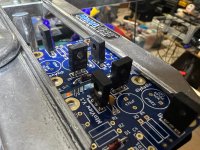
I'm building the mountain view input stage - do I have these transistors oriented right? The "back" ( legs closest to the flat ) lines up with the line on the pcb. I think its right just looking for confirmation!
Next up is the led and resistors.
I am also uilding Ishikawa and Tucson. Not sure which board I'm going to start with but things are progressing 😉 Given the cost Ishikawa goes in well after I've commissioned the amp! I'll probably start with Tucson since its the least expensive to replace if I managed to screw something up.
Attachments
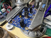
Yes, if everything is perfect, then that's correct re: you're understanding. In fairness, in your photos .. I can't be certain that you followed that practice. Could just be the photos and/or my eyes, but some of them look reversed.I'm building the mountain view input stage - do I have these transistors oriented right? The "back" ( legs closest to the flat ) lines up with the line on the pcb. I think its right just looking for confirmation!
What I'd do in your case (for learning and for quadruple confirmation) is to examine the datasheet for the parts you purchased against the schematic. It shouldn't take more than a couple minutes vs. the potentially lengthy period of repair if for any reason the parts you purchased have a different pin-out than what was used to create the schematic. Rare... but it happens. Then, you'll have every bit of confidence that they're all in properly vs. someone with really bad eyes looking at a photo. Others may be able to look at the photos and the parts designations and tell you with more certainty.
Hello bilsch,
as I see it - Q1 and Q2 seem reversed (180 degrees). The silkscreen shows for the TO-220- devices (transistors) a double line
where should be the backside of the transistor. On the frontside there is the type-number,....
Cheers
Dirk
as I see it - Q1 and Q2 seem reversed (180 degrees). The silkscreen shows for the TO-220- devices (transistors) a double line
where should be the backside of the transistor. On the frontside there is the type-number,....
Cheers
Dirk
As IAIMH says, checking datasheets helps. Especially if you have changed to other transistors. Hmmm
I just looked at my Mtn View boards and Q1, Q2, Q3 are all reversed. As @cubicincher said the "double line" on the case outline is the Back/Heatsink side of the transistor case. - so case writing should be opposite the double lineI'm building the mountain view input stage - do I have these transistors oriented right? The "back" ( legs closest to the flat ) lines up with the line on the pcb. I think its right just looking for confirmation!
Next up is the led and resistors.
I am also uilding Ishikawa and Tucson. Not sure which board I'm going to start with but things are progressing 😉 Given the cost Ishikawa goes in well after I've commissioned the amp! I'll probably start with Tucson since its the least expensive to replace if I managed to screw something up.
Attachments
@bilsch - If I were you... I wouldn't trust anyone's eyes. I'll repeat my recommendation - Check the data sheet and confirm.
As an example -
In your photos, I see a few that I'd say don't look correct or at least don't seem to match between boards. I see a few others that look just fine as I mentioned previously. The only way to know with certainty is to triple check yourself.
I circled what I'd triple check below, but if I were you... I wouldn't trust me as the final decider of whether your amp will work based on a photo and my bad eyes.
Cheers!
Edited to add - What I'd also recommend is orienting both boards the same way as you solder them. That may (or may not) help.

As an example -
This person sees theirs as "reversed" ... I actually see them as correct to the typical practice in their photos.I just looked at my Mtn View boards and Q1, Q2, Q3 are all reversed
In your photos, I see a few that I'd say don't look correct or at least don't seem to match between boards. I see a few others that look just fine as I mentioned previously. The only way to know with certainty is to triple check yourself.
I circled what I'd triple check below, but if I were you... I wouldn't trust me as the final decider of whether your amp will work based on a photo and my bad eyes.
Cheers!
Edited to add - What I'd also recommend is orienting both boards the same way as you solder them. That may (or may not) help.
Last edited:
Hi guys - been interested to build my first DIY firstwatt and was in between the F7 or the M2X
Decided to go with the M2 as it has the official schematics and options for the daughter boards.
I've ordered the board including the universal PSU from diyaudiostore and shipped it to a friend, it would be at least 6 months before he come to visit me in south east asia.
I'm also on my way to read all the 300+ pages of this thread and making notes to the build. I'm not an expert on building amplifier but have done it before.
Currently gathering parts for the main boards, tucson and mountain view.
looking forward to building this!

If you only have dual opamps, then IPS7 as above is your only choice. If you have singles then you could also try them in the Tucson board. And I suppose also Cedarburg, but that would be immensely disrespectful towards the late Scott Wurcer, who designed the AD797 opamp for which Cedarburg is specifically tailored.
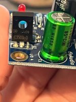
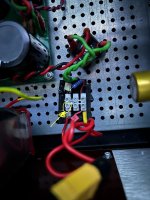
A few years have passed and I got a malfunction. Loose connection in the snubber module resulted in the lack of a positive power rail. It started with a floating offset and ended with 11v on the speaker output. Fortunately, I have RTR Speaker Protection modules. They also earned money for themselves 🙂
By the way, I changed the card to Tucson with LT1122 and decided that it was finally time to finish the other daughterboards
By the way, I changed the card to Tucson with LT1122 and decided that it was finally time to finish the other daughterboards
Attachments

Snubber module?Loose connection in the snubber module
Did one of the connections to the rectifier become dislodged?
I am trying to visualize what could have happened. My guess is that you may have one of the cute snubber boards that slides over the monolithic rectifier pins.
Mainly, I am trying to determine if the failure mode:
- had anything at all to do with the "snubber board" which I find unlikely, or
- if you just had rectifier connection come loose (more likely), or
- it was something completely different.
Thank you!!!
^ Yep, I guessed wrong. Very, very happy you had a DC protect board. That may not have had a happy ending. 🙂 🙂 🙂
Edited to add - Thank you for sharing that photo. Some people do not like to share photos of things that have not worked well. I think we all learn from each other.
Edited to add - Thank you for sharing that photo. Some people do not like to share photos of things that have not worked well. I think we all learn from each other.
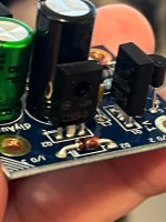
This is my first finished DIY device. Now I would do a few things differently - for example, I would not solder the ends of the wires but used crimp sleeves.
E: You were right - there was no connection with the rectifer bridge
E: You were right - there was no connection with the rectifer bridge
^ You have lived and learned.
You may know it now, but you should not solder multi-strand wire for use in a terminal like you are using. 🙂
I rely heavily on something very close to this. My memory is not perfect, but I am pretty sure @Mark Johnson was the one that recommended that I try it. I got mine in early 2020 according to my purchase history, and it has served me well.
Bootlace Ferrules and Tool
I am not sure of a proper source for them or their cost in your country. I always feel badly posting links to US sources as examples, but ...
Congratulations on your first build. The M2x was also my first First Watt. I hope it provides many more years of beautiful music. Mine is still going strong. Sadly, I still have not made it through trying all of the IPS.
I used exactly the same crimper for the next device - DAC. IPS I used only mountain view and ishikawa and now Tucson .
Yes I was the (M2x + ferrules + specialized crimper + super cheapo assortment at amazon) evangelist. They make life sooooo much easier when wiring up an M2x. I believe ferrules are required by the electrical code in Germany and perhaps elsewhere; bare wire (either stranded or solid) into Euroblox connectors is forbidden.
An underappreciated feature of ferrules is that you can shove and crimp two stranded wires into one ferrule. So you can have Vpos_left and Vpos_right DC power wires to the left and right channels, sharing a single ferrule and a single Euroblox connector position (cage).
An underappreciated feature of ferrules is that you can shove and crimp two stranded wires into one ferrule. So you can have Vpos_left and Vpos_right DC power wires to the left and right channels, sharing a single ferrule and a single Euroblox connector position (cage).
- Home
- Amplifiers
- Pass Labs
- The diyAudio First Watt M2x