It's all in post #1 of this thread. Parts list in a .zip archive, Gerber files in another .zip, schematic image in filetype .png.
Have a batch of PCBs fabbed and offer your extras to other diyAudio members. Or, scroll backwards thru time starting with today, and check whether a member has recently offered HER extra boards, possibly to you.
Have a batch of PCBs fabbed and offer your extras to other diyAudio members. Or, scroll backwards thru time starting with today, and check whether a member has recently offered HER extra boards, possibly to you.
Is there a reason that a 21V Zener is used for the kickback diode for the relay? Just asking because I have some 15V 1N4744 and was thinking of using instead of the spec'd 1N4748, or just using a 1N4001-4007.
Yes there is a reason the 22V 1N4748A Zener diode is used to protect the MOSFET from excess Vds when the relay coil is de-energized.
You only asked yes-or-no-is-there-a-reason, so don't read the following spoiler if you don't want to know why: It dissipates the coil's energy (ramping coil current down to zero mA) about 3x faster.
If you decide to substitute a different protection circuit, make sure you point its diode(s) in the correct direction for proper functionality.
Thanks Mark. I hadn't seen a Zener used for this and wasn't sure why 22V was chosen (on a 5V circuit). Would the 15V 1N4744a zeners I already have work? Normally I just see (and use) standard diodes such as the 1N400x series across the coil. I'm using a version of your board, with your schematic, so the diode is in the correct direction.
Again Thanks Mark for this design.
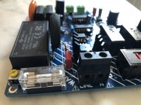
That is the new board to Follow my need and to be conform to EU regulations ( one Main switch and relay contacts in both L and N lines)
In switched off state there will never be any voltage on the primary windings of connected transformers.
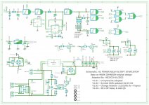
I have finish and tested the Board with 4 layers. The PCB Included a GLB circuit for the AMP PSU, and a +5Volt regulated.
The digital logic are powered from a AC-to-DC converter module.
PSK-6B-S12 From CUI is the one I selected, that is a 12V model, i could also selected MP-LDE06-20B12 from MULTICOM with the same footprint


That is the new board to Follow my need and to be conform to EU regulations ( one Main switch and relay contacts in both L and N lines)
In switched off state there will never be any voltage on the primary windings of connected transformers.
I have finish and tested the Board with 4 layers. The PCB Included a GLB circuit for the AMP PSU, and a +5Volt regulated.
The digital logic are powered from a AC-to-DC converter module.
PSK-6B-S12 From CUI is the one I selected, that is a 12V model, i could also selected MP-LDE06-20B12 from MULTICOM with the same footprint
Attachments
Last edited:

Congratulations and thank you for making every aspect of your design available to all members!! Very well done.
It's interesting to see that you decided to use relays with 12 volt coils instead of 5V relays as in post #1. I've been having poor success trying to source 12V relays, the ones I'd like are 100% out of stock and backordered for months. Everywhere I look. Maybe 5V relays have become sold out too... For the Tuba high power regulator board, I actually used a relay with 24VDC coil, but that board has no CD4000 logic chips (VDDmax = 15V).
It's interesting to see that you decided to use relays with 12 volt coils instead of 5V relays as in post #1. I've been having poor success trying to source 12V relays, the ones I'd like are 100% out of stock and backordered for months. Everywhere I look. Maybe 5V relays have become sold out too... For the Tuba high power regulator board, I actually used a relay with 24VDC coil, but that board has no CD4000 logic chips (VDDmax = 15V).
Right now there are some 5V available here: G5RL-1A4-E-TV8 DC5 BY OMZ
and 12V here: RTD34012F or G5RL-1A4-E-TV8 DC12
But may be not for long.
and 12V here: RTD34012F or G5RL-1A4-E-TV8 DC12
But may be not for long.
Again Thanks Mark for this design.
That is the new board to Follow my need and to be conform to EU regulations ( one Main switch and relay contacts in both L and N lines)
In switched off state there will never be any voltage on the primary windings of connected transformers.
I have finish and tested the Board with 4 layers. The PCB Included a GLB circuit for the AMP PSU, and a +5Volt regulated.
The digital logic are powered from a AC-to-DC converter module.
PSK-6B-S12 From CUI is the one I selected, that is a 12V model, i could also selected MP-LDE06-20B12 from MULTICOM with the same
These are great designs and will hopefully become part of a new amp build.
But first does anyone know if the EU regs mentioned in this post are still the same as the UK ones? There were I'm told last year?
I had PM for spare Board..
So to anyone interested i have 3 spare left (1.04 version) You just have to share the cost 12.5€ for one Board and to paid the post stamp with tracking 6€ (EU preferred) PM if interested!!


So to anyone interested i have 3 spare left (1.04 version) You just have to share the cost 12.5€ for one Board and to paid the post stamp with tracking 6€ (EU preferred) PM if interested!!
Many thanks Mark Johnson for sharing. Very good idea it is even worse for me as my iec plug behind the case sometimes as no on/off and I just plug unplubg the main wire, uh !
Thanks also Hicoco, I am Europe 230 VAC as well.
Is your circuit could be helpfull also for a HIT heater and B+ power supply as well to not stress a NOS tube, please ?
I think about the soft start behavior and inrush limiting with the low impedance of the filament at starting. If the ECC88 is a low voltage tube (understand: not as a DHT) and does not really need all those protections I was said, it could not hurt for the lifespan, no (I often power my hifi for less than hour because missing of daily time) ? As it is a tube used in a dac as I/V behavior, the board could be put at the AC input of my dac which has several traffo for a total of 300 VA ?
Good idea or just it doesn't worth here and just usefull for big inrush for the amps only?
I have no experience, insight, or intuition about vacuum tube circuitry, sorry. I think it'd be a good idea to search around in the valve/tube area of the Forums, to see whether soft start has already been discussed. If not, you can always start a new thread there, and solicit the assistance of real experts. It seems likely that lots of people have had the idea to marry soft start + valve heaters, over the years.
Last edited:
I had an answer on the tubes forum section. Answer is it is not usefull but for amps (here tubes amp with SS rectification ) as you illustrated in your post#1 examples with the joules involved.
The mains inlet switch is ON at all times, and I turn the audio equipment on and off using the low voltage front panel switch.Unfortunately, what you are doing is exactly the opposite of what the AC mains relay & soft start board expects.
The board expects that you will leave the mains inlet switch ON at all times, and will turn the audio equipment on and off using the low voltage front panel switch.
The board contains an "always on" 5V DC power supply, carefully selected to meet international standards of ultra low standby power. And the circuit design assumes this 5V power supply is always on, namely, that it is always connected to the AC mains. But you are switching it off (and on) from the inlet switch. That was not forseen, indeed it was not even imagined, when I designed the circuit. Don't do that!
Couple time i lost the power and when the power went back ON, i had noticed that the fuse blow each time.
Recently I simulated the power cut and for couple of ms (hard to say for how long, that is very short time) the relays are switched on and off.
I plan to design a little Add-On close to the output connectors with a on-delay for 1ms or 2ms directly connected to the AC/DC power module output. May be you have a better idea?
Last edited:
I think you might want to redesign the digital logic section of your board. You'll have two more state transition diagrams besides the two shown in post #1 of this thread and copied below.
One of the new state transition diagrams begins with "Mains power is lost while front panel switch is ON", and shows the sequencing you need your redesigned circuit to perform, in order to avoid blown fuses. Another new diagram begins with "Mains power is restored while front panel switch is ON" and shows your sequencing for the redesigned circuit, which prevents fuse blowing.
Remember that the +5V housekeeping power supply doesn't function when there is no mains power. It's an AC-to-DC converter and when the AC is absent, so is the DC.
_
Attachments

Thanks Mark,
I forgot to mention that I use a momentary switch, when the power is restored the audio equipment stay OFF, I have to turn the audio equipment back ON using the low voltage momentary switch.
I understood well that the +5V (+12V for my board) housekeeping power supply doesn't function when there is no mains power.
I believe also that happened to other builder..now i am not sure if the fuse blow.
I also updated the design with a On-delay of 1ms at the first time mains power ON and when the power is restored after been lost.
I don't see much option for the others boards already build, that of add an mains power on-delay with a new small board.
Dear Mark,
I’ve a question for you 🙂
My board is connected to mains throught IEC inlet with double pole switch and I have a 400VA 18+18v transformer with DIYAudio Power supply v3 connected to it
When I turn it on with the mains inlet switch some current flows to the transformer and there are about 10v DC at the power supply output. This will slowly goes to zero while the capacitors discharge.
- Home
- Amplifiers
- Power Supplies
- PCB: low voltage On-Off switch drives AC mains relay \ includes soft start .. H9KPXG