
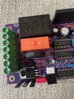
Drain current is about 21mA or so.Q3 on both units are running at about 50C case temp
Rds_on is about 10 ohms.
Power dissipation is thus about 4.5 milliwatts
Theta_ja is 132 degrees C per watt
Thus junction temperature should be about 0.6 degrees C above ambient air temperature
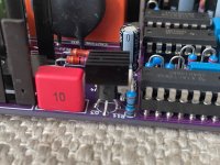
One way to make it run a lot hotter is to replace R11 by a resistance a lot less than 180 ohms. Maybe your R11's are the wrong value?
Mark:
I checked and R11 is 180 ohms as specified. Any thing else that could drive these so hard? My load is an 80W light bulb.
I checked and R11 is 180 ohms as specified. Any thing else that could drive these so hard? My load is an 80W light bulb.
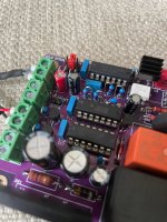
R11 is scorching hot. Just measured voltage across it...13.5V. Into 180 ohms that is 1 watt of power. All advice is welcome.
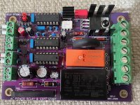
Attachments
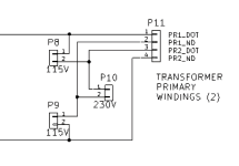
Yes, you are correct. I will be using a single 120V primary transformer. Connecting to PR1_DOT and PR2_ND works fine for my scenario without the use of jumpers.
- Home
- Amplifiers
- Power Supplies
- PCB: low voltage On-Off switch drives AC mains relay \ includes soft start .. H9KPXG