I purchased a batch of the H98KPXG boards a few months back and am selling some extras off. More details in the Swap Meet section.
https://www.diyaudio.com/community/...t-boards-by-mark-johnson.418013/#post-7799532
https://www.diyaudio.com/community/...t-boards-by-mark-johnson.418013/#post-7799532
As part of a crazy large JLCPCB order, I purchased over 100 of Mark's H9KPXG boards and got a really good price break. I'm sharing the savings with boards for sale in the swap meet.
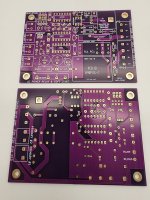
H9KPXG Soft Start On/Off Switch
H9KPXG Soft Start On/Off Switch
- Purple board color
- EING Finish
- 2oz outer copper
- 1.6mm thickness
Attachments
Last edited:

Is it O.K. to use this on an amplifier that has power coming an ANTEK BP-1300 Balance Isiolation Power Supply ?
Typically you'd install a soft start board between the AC mains and the transformer primary. Or if there are several transformers connected in series, between the AC mains and the first transformer's primary. That's because it's possible that you'll switch ON at exactly the worst case phase of the mains sinewave, causing a giant inrush current as you drive the core magnetization. Even if there are no electrolytic capacitors downstream, the transformer "iron" itself can cause an inrush. So you put the soft start upstream of the "iron", i.e., upstream of the first transformer in the chain.
Mark - my concern was, with balanced power boxes, they are putting out two lines of 60 volts, instead of a line (120V) and a neutral ( 0 V). That would mean the amplifier with a H9KPXG installed, one side of the amplifier’s transformer primary, and pin 2 of the IRM Module, would always be seeing 60 volts when the amplifier is off.
To date, I have not had any issues with balanced power feeding amplifiers with transformers, and other components that have internal Switching power supplies ( with AMY ALICE’S !! ).
Just wanted to double check on the H9KPXG being O.K. with 60 volts going to the neutral line with power switch off.
To date, I have not had any issues with balanced power feeding amplifiers with transformers, and other components that have internal Switching power supplies ( with AMY ALICE’S !! ).
Just wanted to double check on the H9KPXG being O.K. with 60 volts going to the neutral line with power switch off.
Unless the BP-1300 is always on and a device with power transformer is the switched load.
Balanced isolation transformers are a special category. Not only is N separated from PE (besides galvanic isolation this is normally their purpose) but also the middle point of output winding is connected to PE thereby ending the gained galvanic isolation. This is quite different from medical isolation transformers and would here 100% for sure not be called “isolation” or “safe” but we don’t have UL here. With the usual medical isolation transformers one can touch either N or L standing with bare feet on the ground without consequences. With the Antek touching either L or N is dangerous! Even more risk than without it. The big question is what is exactly gained by connection of the middle point to PE. IMHO nothing. Zero. 0.
Schematic is on the last page.
https://www.antekinc.com/bp-1300-balance-isiolation-power-supply/#PhotoSwipe1730372193455
Last edited:
Which seems like the normal mode of operation for that device.Unless the BP-1300 is always on and a device with power transformer is the switched load.
No you need a double pole circuit so both L and N switched. Switching both L and N is also the usual safe method and therefor mandatory in the EU. This to avoid a seemingly powered off device to still have L connected to the transformer. This may happen with "non-polarized" plugs and wall sockets.Mark - my concern was, with balanced power boxes, they are putting out two lines of 60 volts, instead of a line (120V) and a neutral ( 0 V). That would mean the amplifier with a H9KPXG installed, one side of the amplifier’s transformer primary, and pin 2 of the IRM Module, would always be seeing 60 volts when the amplifier is off.
To date, I have not had any issues with balanced power feeding amplifiers with transformers, and other components that have internal Switching power supplies ( with AMY ALICE’S !! ).
Just wanted to double check on the H9KPXG being O.K. with 60 volts going to the neutral line with power switch off.
Switching only one leg is not electrically safe and definitely not in your case with half the mains voltage always energizing stuff.
Last edited:
No. Can not speak for the complete EU and all devices but in the countries I know it is like that in most devices for quite some years now. Harmonisation is ongoing. Industrial single phase devices (definitely the kind that needs to be maintained) have double pole switches. IF the equipment has a true mains switch that is. Many devices are switched electronically and are therefor considered energized when plugged in similar to equipment that has a permanent connection.
There are exceptions in industrial situations particularly 3 phase stuff where disconnecting N may not lead to success.
Anyway in the case of H9KPXG one can say that the device it switches on/off is not de-energized in off situation.
There are exceptions in industrial situations particularly 3 phase stuff where disconnecting N may not lead to success.
Anyway in the case of H9KPXG one can say that the device it switches on/off is not de-energized in off situation.
Last edited:
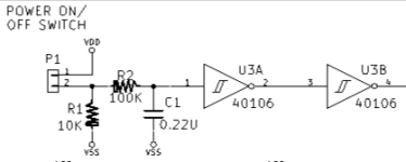
After power button released, debounce cap is discharged creating delay time for the release. Is that on purpose?
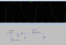
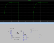
Played in sim and found solution to keep debounce delay on button push and no delay upon button release.
Voltage probed before Schmitt trigger.
Played in sim and found solution to keep debounce delay on button push and no delay upon button release.
Voltage probed before Schmitt trigger.
Attachments
Which switch motion produces more (longer lasting) switch bounce transitions? On-to-Off? Off-to-On? Why do you say that?
Defend your choice. And then calculate the timeconstant when R=1E+5 and C=2.2E-7. How many seconds is that?
Defend your choice. And then calculate the timeconstant when R=1E+5 and C=2.2E-7. How many seconds is that?
Hoping to get some help on a soft start board problem I’m having.
I have a dual mono Aleph J using two soft start boards witu a push switch that has two separate poles.
When I push the power button the right channel automatically kicks on while the left channel has the correct delay.
It’s been like this for awhile and I’ve finally decided to troubleshoot.
I pulled the faulty board and did some solder checks and it all appears to look good.
Attempted to flip the boards the the left channel board worked correctly on the right channel side.
I had a spare board stuffed up that I had not tested yet so I popped it in but same problem. No delay and the amp channel pops on right away.
Any good way to troubleshoot this?
I examined each Soft start board and this is what I found.
One thing I noticed in the problem board is that when I hook up my power cable and turn on the IEC master switch on the back, the LEDs on the PSU automatically light up like there is some AC leaking through.
Maybe my boards were working correctly, but the 220k vs 200k resistors make them operate so different with both being turned on by the same switch.
- The left board with a 2 second delay has R8 and R13 as 220k and NOT 200k in the BOM
- The other board that does not have the long delay has the 200k resistors in R8 and R13 (as soon as I push the anti-vandal switch the amp starts playing).
One thing I noticed in the problem board is that when I hook up my power cable and turn on the IEC master switch on the back, the LEDs on the PSU automatically light up like there is some AC leaking through.
Maybe my boards were working correctly, but the 220k vs 200k resistors make them operate so different with both being turned on by the same switch.
I think you'd like to know whether the problem board fails to delay correctly, on the other settings too. With jumper set for 0.5 sec, does the board operate correctly? With jumper set for 1.0 sec, does the board operate correctly?
You entertain the hypothesis that R13 (200K) might be causing a problem. Perhaps it's also important to entertain the hypothesis that C9 (10uF) might be causing the problem. If C9 is faulty then ALL delay settings will be effected. The experiment above will shed light on this. Another hypothesis is that U3F or U5D might be causing the problem. If either of them is faulty then ALL delay settings will be effected. The experiment above will shed light on this.
And of course the most likely suspect is that P7 or R13 are poorly soldered. Divide and conquer as mentioned above, can help narrow the field of suspects.
- Home
- Amplifiers
- Power Supplies
- PCB: low voltage On-Off switch drives AC mains relay \ includes soft start .. H9KPXG