Perhaps use your DMM set to continuity and see if both fuses are required.
The picture is a bit challenging, but I concur with 6L6. You almost certainly have your IEC / switch wired incorrectly. Once again, a DMM set to continuity will confirm.
If you are unsure... here is how to check...
With no mains power connected...
Plug your power cord into the IEC. You should know which pins are live, neutral and ground. If you don't, stop, and look it up.
Remove all your wiring on the "back" side of your IEC / Switch.
Put one DMM probe onto each pin of your power cord.
Ensure a proper physically-sized fuse with continuity is placed into each of the slots.
Trace each power cord pin to where it transfers into the "back" side of your IEC. Mark each of those points using your choice of indicator on the back of the IEC. Confirm with a continuity check to each pin on your power cord. You should now have a ground, live, and neutral marked.
Remove fuses one at a time, and see if the continuity maintains to each of those points. That should answer your question.
Now to see if your switch was wired correctly...
Check which pins on the IEC / switch have continuity with each other. Flip the switch and see if that changes. Note that the intended switched output are the "top". You have already marked where the power comes in.
If you want to carry the current from the 'bottom', un-switched section to the 'top', switched section... while maintaining the relative left to right orientation of the live and neutral, where would you put the jumpers?
Install your jumpers. Check that you were correct by flipping the switch on and off. With the switch "on" do you now have continuity between the bottom section and the top section for your live and neutral? If so, mark them accordingly.
Install your "output" live and neutral into the top positions ensuring relative orientation of live and neutral. Your continuity checks between all pins have revealed that there are options, but one is certainly "cleaner" than another for your wire routing. I like 6L6's example in your pictures.
Check that you have continuity all the way from the pins of your power cord all the way to your intended live and neutral points as they enter the first functional circuit in your amplifier.
If so, reinstall your ground and check for continuity to all points where you intend to have chassis / mains earth ground.
If you do not, you may have a bad IEC / switch and/or additional trouble shooting is needed.
Note - you stated that you applied power before doing something like this to ensure you had it wired correctly. I'd avoid that practice in the future. You got somewhat lucky. Messing with mains power w/o a fundamental understanding is SCARY (to me).
Last edited:

Do everything above first, then install a jumper on momentary pins. It will not start if you don't have a jumper across the momentary pins with a momentary switch.
Ok. I've got a diyaudio IEC installed wired per the guide as attached.
When I turn the IEC on in back, the LED light on the slow start board lights up. But when I push the on button in the front panel on, I don't hear the click and I only measure 2-3 VDC. This holds true for 4 scenarios:
I have two different slow start boards and two different PSU board. I get the same results across all four of them.
I'm missing something very basic here, but I'm not seeing it.
Appreciate any comments.
Attachments

It has something to do with the switch. Either it's wired wrong or is a momentary type. Post switch part number and schematic.
You can test the switch with an ohm meter. switch it on and check across the common to NO pin, it should be very close to zero, less than .5 ohms and of course infinite when you switch it off.
Are you assuming this because only one fuse blew out of the two? If so, that's not sound reasoning. Your kit should have come with a 3A slow and a 10A fast. Please be sure you put them in the proper slots.2 fuses: fuse on right facing front of IEC is live, the other a spare. I know because I blew one out.
Did you confirm the fused line(s) with a DMM per previously provided instructions? Asking because A) it's important and B) if you got the part as part of the back panel kit from the store, having only one line fused is unlikely, but not impossible. If it is only one, then they've swapped parts. It's good to be sure and choose each fuse value appropriately / accordingly.
Edited to add - confirmed through a highly reliable source that the part should in-fact be fused on both live and neutral. Either you've assumed incorrectly, didn't measure per instructions, didn't measure at all, you've received the wrong part from the store, or I misread that you got the part from the DIYA store as part of the back panel kit.
Last edited:
ItsAllinMyHead,
Thanks for your comments. I wish it were all in my head!
Your comments are very helpful.
The IEC I'm using is the 6765 same as listed at diyAudio. Not sure when I acquired a bunch of them.
I have not used them before.
I was using 2.5 Slow Blow fuses in both slots.
I assume the 3A slow goes in the right slot [with IEC front facing] and the 10A fast in the left slot.
I will acquire some fuses and go back and do the testing you laid out in #581.
Thanks again.
I just stumbled across this excellent project, great work! I'm looking to purchase 3 PCBs if anyone has spares.
Hello Hicoco!The mains inlet switch is ON at all times, and I turn the audio equipment on and off using the low voltage front panel switch.
Couple time i lost the power and when the power went back ON, i had noticed that the fuse blow each time.
Recently I simulated the power cut and for couple of ms (hard to say for how long, that is very short time) the relays are switched on and off.
I plan to design a little Add-On close to the output connectors with a on-delay for 1ms or 2ms directly connected to the AC/DC power module output. May be you have a better idea?
I was wondering if you found a good solution to the "sudden loss of power" problem? (with this otherwise very nicely designed board)
I see that Mark J. had this suggestion:
"One of the new state transition diagrams begins with "Mains power is lost while front panel switch is ON", and shows the sequencing you need your redesigned circuit to perform, in order to avoid blown fuses. Another new diagram begins with "Mains power is restored while front panel switch is ON" and shows your sequencing for the redesigned circuit, which prevents fuse blowing."
- Did you try and implement this in the design, or did you add "simply" something to the board for delay?
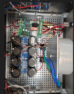
Yes with something very simple (I do not lost the power often), i just added a little output circuit with on-delay when the power come back. I also designed a new board with this function (red oval circle).


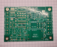
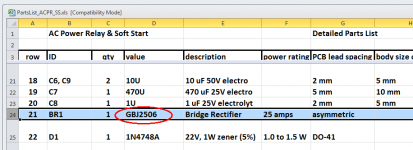
This PCB (id = H9KPXG) is designed to use a GBJ2506 bridge rectifier, as shown in the Detailed Parts List attached to post #1 of this thread (see image 1 below). This particular component is in the "GBJ" package, sometimes written "GBJ-4", and that's what the H9KPXG circuit board is designed to accept.
Because the circuit externally connects the bridge in such a way that its diodes are wired back-to-back, the datasheet reverse voltage rating is not terribly important. Diodes within the bridge will turn on whenever the external voltage exceeds +2V (or -2V) so even a 50V rated bridge is sufficient. I only specified the 600V model ( GBJ2506 ) because it had huge numbers of parts in stock when I built the prototype, in April of 2020.
Since the purpose of this bridge is to protect the user when a certain type of AC mains fault occurs, the bridge's current rating should exceed the home circuit breaker / fuse's rating. I picked 25 amperes . . . but there are some 50 amp bridges in stock today in the GBJ-4 package, at mouser.com. In the US where houses have 15 amp circuit breakers, any bridge rated for 16A or greater, would offer good protection. And 50 is certainly greater than 16.
_
Attachments
- Home
- Amplifiers
- Power Supplies
- PCB: low voltage On-Off switch drives AC mains relay \ includes soft start .. H9KPXG