Thanks, found GBJ2506-G for the H9KPXG board.
Any replacement for the following?
TP2104N3-G and TN2106N3-G
CD4001BEE4
SL22 50004 for 230VAC
Any replacement for the following?
TP2104N3-G and TN2106N3-G
CD4001BEE4
SL22 50004 for 230VAC
Last edited:
Can the SL15 60004 with 60 ohms be used as a substitute? Or is the SL15 40004 with 40 ohms a better replacement?SL22 50004 for 230VAC
Both are 230VAC.
Last edited:

Very nice page, thanks. Ended up with pretty similar to what Mark has proposed for 230VAC: 60 ohm 4AYou should read that to select your thermistor: Transformer Inrush Current Calculation
Any possible replacement for the TP2104N3-G and TN2106N3-G
Everything else I already substituted.
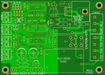
Looks like you've eliminated the user options to connect the transformer primaries either in series (230VAC) or in parallel (115VAC). Also looks like you've changed to a different AC-to-DC converter device, and as you noted, converted some thru-hole resistors & capacitors to surface mount.
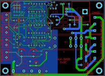
Checked, only 2 layers.
https://www.pcbway.com/project/shar...mains_relay_includes_soft_start_2e05ee9f.html
If you do not have the opportunity to order printed circuit boards on PCBway, I can share gerbers here no earlier than a month later.
https://www.pcbway.com/project/shar...mains_relay_includes_soft_start_2e05ee9f.html
If you do not have the opportunity to order printed circuit boards on PCBway, I can share gerbers here no earlier than a month later.
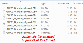
Attachments

If you are in the EU, you should check out post #550.I got used to that I have 230V AC in my network. The converter used more affordable, IRM-02-05 did not find on sale.
Hi Hicoco, could you please post the gerber for your improved v1.06 board and maybe an update on Q6, Q7, C15, R17, R18 values.Yes with something very simple (I do not lost the power often), i just added a little output circuit with on-delay when the power come back. I also designed a new board with this function (red oval circle).View attachment 1093398
That would be awesome. Thank you very much!
Thank you, Hicoco, appreciated!Updated UE version with add-on
Btw, why is it called UE version?
Not sure if this has been answered, so excuse me for asking again if it has. I am testing a board I acquired and almost done populating a second for a pair of F4 amps I am building. I got the switch led on and off working correctly, but I noticed the soft start is still allowing voltage to the primaries after being switched off.
Any help is appreciated
Any help is appreciated
Are you testing it without a load?
It's working!
Use a load (say 1W, 75k to 100k resistor) across the P1D/P1N or P2D/P2N terminals and it will work. Or if you have a light bulb, it should be good too.
It's working!
Use a load (say 1W, 75k to 100k resistor) across the P1D/P1N or P2D/P2N terminals and it will work. Or if you have a light bulb, it should be good too.
Ok. Good to know. I just installed a transformer and diode bridge to check DC voltage. I am getting 19VDC with the unit on, but when turned off I still see 4VDC at the diode bridge.
The diode bridge is on the other side (secondary) of the toroid so that's a different story. I thought you are testing the H9KPXG board only at this time. IMO, you are good to go and it is definitely working. Enjoy!
- Home
- Amplifiers
- Power Supplies
- PCB: low voltage On-Off switch drives AC mains relay \ includes soft start .. H9KPXG