Just hooked mine up for the first time, and I'm getting power through to the transformer connections even when the switch is off. Where should I look for diagnosing this?
How many posts in this thread have you read so far?
Quite a few, though most of it was back when I first assembled it. I’m only using P1 and have a 150k ohm resistor across P2.
Right now when the switch is off, I read 4.4VAC on P1 and an LED on a downstream board is very dimly lit. Is 150k ohm too high? I think I remember 100k ohm being what people used.
Perhaps a related issue, but when I turn the switch on and I get full voltage through P1 (regardless if there’s is a load or not), there’s a faint high pitched ringing sound.
Post#65
I'm fairly sure I have mine configured that way? I have my transformer in P1 and a 150k ohm resistor across P2. My concern is not what I'm reading on my DMM, but the fact that LEDs in the amp are dimly lit, meaning at least some voltage is getting through.
I could live with a nominal amount of voltage coming through, the biggest issue is the high pitched whining. Reminiscent of old CRT TVs or something.
Folks:
A dumb question, perhaps, but I'm unclear about the functional differences between ceramic and electrolytic capacitors. Here's my question: can a ceramic cap be substituted for the electrolytic cap at C8? Same value, higher voltage (not surprisingly). I have 1 uF ceramics on hand but no 1 uF electrolytics.
Thank you,
Scott
but I'm unclear about the functional differences between ceramic and electrolytic capacitors.
In general, ceramic capacitors don't like DC bias and the capacitance will drop if DC voltage is near max voltage rating of capacitor. For MLCC this can be up to 80% of capacity. To overcome this, voltage rating should be greatly oversized. That is, if the capacitance value is important. Another difference is that ceramic capacitors have low ESR, which often is a good thing, but in some applications designed for electrolytics could cause instability (some examples could be in switching applications or regulators that specify certain ESR range for output capacitors).
Since in this case C8 is used together with R16 as RC delay using a ceramic capacitor (with lower capacitance due to DC bias) would probably shorten the delay.
Here's the information that members @johan and @bohrok2610 need, to formulate their own certain and unambiguous yes-or-no answer, without equivocation or caveats.
_
_
Attachments

Yes, a 1.0uF ceramic capacitor rated more than 25 volts, accidentally turns out to be okay in the C8 position of that particular circuit, at its operational signal swings and for its specific function.can a ceramic cap be substituted for the electrolytic cap at C8? Same value, higher voltage (not surprisingly). I have 1 uF ceramics on hand but no 1 uF electrolytics.
You can further increase the likelihood of success, by
* Choosing a ceramic cap whose dielectric is "X7R" -- by far the best of the schlock (non NP0/C0G) dielectrics for 5V digital circuits
* Measuring its capacitance on a Mega328 Component Tester (or your multimeter) and ensuring the meter reading is within 20% of 1.0 microfarad
btw, eBay sells the Mega328 for a lot less money than Amazon
Mark:
Thank you for the thorough reply! I have exactly the part on hand (and will measure it first with the Mega328 component tester I bought on a whim a few years ago).
Regards,
Scott
Thank you for the thorough reply! I have exactly the part on hand (and will measure it first with the Mega328 component tester I bought on a whim a few years ago).
Regards,
Scott


Nice catch Mark. I really do need to order one, no problems yet, but it is just a matter of time.
I recently ported my F5 amp from a 5U to 4U chassis. That would seem to be straight-forward?
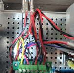
I moved everything over. It was all working before I removed it.
But for the life of me, I can't get any current in and thru the PSU to measure.
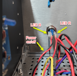
The stand-by LED doesn't light when I turn the amp on in back, and when I press the on/off button, nothing.
I've double checked everything, but obviously I'm missing something. The fuse is in and is good.
I'd appreciate all thoughts and prayers....
[Mark, thanks again for this wonderful board. I'm using it in four Pass amps and 2 Pass pres.].
I moved everything over. It was all working before I removed it.
But for the life of me, I can't get any current in and thru the PSU to measure.
The stand-by LED doesn't light when I turn the amp on in back, and when I press the on/off button, nothing.
I've double checked everything, but obviously I'm missing something. The fuse is in and is good.
I'd appreciate all thoughts and prayers....
[Mark, thanks again for this wonderful board. I'm using it in four Pass amps and 2 Pass pres.].
Attachments

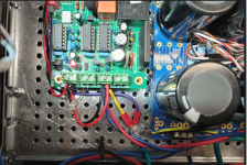
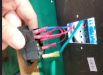
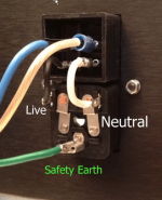
I’m not exactly sure what IEC inlet that is, but if it’s the one from the store’s back panel kit, it doesn‘t appear to be wired properly.
I'm showing the IEC and wiring I was using in my F5. I've found a wiring guide from the F5 build guide and I have an IEC that is from diyaudio, I think. I'm showing the new wiring schema. This IEC has two fuses that are active? Or is one active and the other the spare?I’m not exactly sure what IEC inlet that is, but if it’s the one from the store’s back panel kit, it doesn‘t appear to be wired properly.
Attachments
![new IEC [2].png](/community/data/attachments/987/987063-cc867275f47738b2fc43a0ed2d050208.jpg?hash=zIZydfR3OL)
- Home
- Amplifiers
- Power Supplies
- PCB: low voltage On-Off switch drives AC mains relay \ includes soft start .. H9KPXG