I ordered all the 3 chips direct from Ti with quick and cheap shipping. Maybe worth a look
Just the other day, I established an account at TI to order three CMOS logic chips I needed for a repair job. The package should arrive tomorrow. I'm glad they offer such a service since the parts are no longer carried by distributors. I know I won't be getting counterfeit parts from ebay or elsewhere.
Thanks, Mark. if i understand well your schematic. Could you confirm that the BT139 is back ON with delays (R16/C8) after the circuit is switch OFF
I set up an account a couple years ago when they had the 50% discount on the TPA3255EVM. That took forever to be delivered.....months....but was worth the wait and the discount.Just the other day, I established an account at TI
I ordered 10 each of the chips at about £0.35 each and £5 delivery which took no time at all. Winner.!
Sorry, i am bad. Just saw that the MOC3063 is activated with a P-Channel Mosfet.Thanks, Mark. if i understand well your schematic. Could you confirm that the BT139 is back ON with delays (R16/C8) after the circuit is switch OFF
I'm using the H9KPXG in my BA-3 preamp. Works like a champ.
I'd like to move to the Khozmo 64 steps relay-based ladder type attenuator with remote.
This set-up requires a 5VDC feed. I thought I could just use the 5Vdc from the board. But the Khozmo requires linear power supply, not SMPS. I'm trying to work out how to provide a linear power supply. I'm hoping I can use the Glassware LV-Regulator set to 5VDC which is currently sold out.
If that all holds together, I'm stumped as to how I feed or connect a 2nd transformer for the LV from the H9KPXG?
Also, I have three boards left from the order I placed last fall. Happy to pass on at cost. The boards work because I've built six of them and using them in my amps and preamps. Send me a PM.
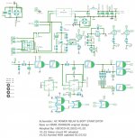
Thank you to Mark for sharing this design, So in the same spirit of customization I've taken this design to made 12V version with 2 relays, with a minor difference.
This is something that I really need to apply to a pair of APEX SR200 with a 625VA transformer.
I also need 12V for this project.
The CD40106 with 12V have a larger Hysteresis Voltage ( ~2,5V with 12V and 0.9V with 5V) so i readapted the R/C circuit to choose one of 3 possible delays (0.5, 1, or 2s). i can also adjust shorter or longer with the selector who have the possibility to have 2 or 3 resistances an parallel, I have to work and test little bit more to adapt better the values.
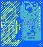
I'd like to get any comments on the PCB design before I send it to be manufactured. I should have spare PCBs if there's any interest in this version, and can share the Gerber files too.
I will do also an other version with 4 layers to double the high voltages tracks on the PCB.
Thanks
This is something that I really need to apply to a pair of APEX SR200 with a 625VA transformer.
I also need 12V for this project.
The CD40106 with 12V have a larger Hysteresis Voltage ( ~2,5V with 12V and 0.9V with 5V) so i readapted the R/C circuit to choose one of 3 possible delays (0.5, 1, or 2s). i can also adjust shorter or longer with the selector who have the possibility to have 2 or 3 resistances an parallel, I have to work and test little bit more to adapt better the values.
I'd like to get any comments on the PCB design before I send it to be manufactured. I should have spare PCBs if there's any interest in this version, and can share the Gerber files too.
I will do also an other version with 4 layers to double the high voltages tracks on the PCB.
Thanks
Attachments
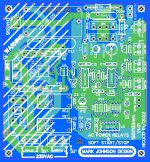
Have you double checked your PCB's minimum "creepage" and "clearance" for 230V mains safety? I'm by no means an expert myself.
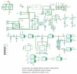
For people who are thoroughly familiar with digital design and reading schematics of digital circuits, your incorrect use of "NAND" gate symbols for the CD4001, will be confusing and irritating. CD4001 is a quad NOR gate; drawing it as four NANDs misleads people. Post #1 of this thread shows the standard NOR gate symbol.
For people who are thoroughly familiar with digital design and reading schematics of digital circuits, your incorrect use of "NAND" gate symbols for the CD4001, will be confusing and irritating. CD4001 is a quad NOR gate; drawing it as four NANDs misleads people. Post #1 of this thread shows the standard NOR gate symbol.
Thanks to point me on this mistake i have updated the schematic with the right symbol, i saw also the Triac T1 have a wrong connection ( reversed). Yes i have enough clearance for 230V mains safety, i have 1mm and more .
Attachments
Hi..
Thanks for this nice project.
Can we use an auxiliary transformer instead of the AC-DC SMPS module?
Thanks and regards,
Sumesh
Thanks for this nice project.
Can we use an auxiliary transformer instead of the AC-DC SMPS module?
Thanks and regards,
Sumesh
Rod Elliott's (project 39) is a soft start circuit using an auxiliary transformer instead of an AC-to-DC SMPS. Which means: yes, it can be done. You'd have to create a new circuit board and include the diodes, filter capacitors, and transformer. I always liked the looks of those tiny blue cubes made by Block Transformers, maybe one of them might fit into your plans. They're available at Newark but not Mouser or DigiKey.
_
_
Attachments

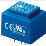
Thank you,Rod Elliott's (project 39) is a soft start circuit using an auxiliary transformer instead of an AC-to-DC SMPS. Which means: yes, it can be done. You'd have to create a new circuit board and include the diodes, filter capacitors, and transformer. I always liked the looks of those tiny blue cubes made by Block Transformers, maybe one of them might fit into your plans. They're available at Newark but not Mouser or DigiKey.
_
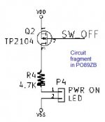
I wish to build this project. Request to suggest any alternatives for TP2104 FET. This FET is not available here.
Regards,
Sumesh
Found the following P channel devices, all are SMD package, wish to find a through hole deviceThank you,
I wish to build this project. Request to suggest any alternatives for TP2104 FET. This FET is not available here.
Regards,
Sumesh
Attachments
I'd suggest you investigate the ZVP series of thru-hole Pchannel MOSFETs from Diodes Inc. DigiKey lists more than 20 different part-numbers. ZVPs are famous for their extreme sensitivity to static / ESD, and many DIYers have inadvertently blown one up. Member / Advisor / Moderator 6L6 recommends that you "buy 5 when you only need 2", just to have spares handy. The Pearl 2 phonostage uses these parts, and it sounds fantastic. For 5V operation you'll get the largest safety margin with low-Vthreshold parts, and those seem to be the ones whose part number begins with "ZVP4". Lots of units in stock today at US DigiKey.
Getting a parts order ready for one of these, and a quick question: the MOC opto isolator doesn't show an IC socket in the Mouser BOM. Is there any reason for not socketing this part? I searched thru the thread, but didn't come up with any mention of that.
There's no special reason, just inertia. Opamps are socketed so the builder can swap in different chips and listen for differences. Logic chips are socketed because builders often buy gray market logic parts and they fail more often than other semiconductors. Thru hole microcontrollers are socketed for reprogramming. DAC and ADC chips are socketed because they're expensive and you want to salvage them when discarding a board. None of those reasons are directly applicable to an opto-triac. But if you want to socket it anyway, go right ahead. Remember that it has 6 pins, not 8.
BUILDER REQUEST: HELP ME INVENT A WAY TO OMIT THE PCHANNEL MOSFETS
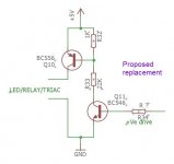
I received a Private Message from someone who wants to copy the PO89ZB circuitry into a new project, except replace the Pchannel MOSFETs with all-bipolar substitute circuits. Since I believe that ten thousand heads are better than one, and the collective experience and wisdom of the Forum vastly exceeds that of any one member, I am moving that request out of Private Messaging and here into the public Forum. Would anyone like to answer this person's inquiry?
Is the active-high-input BJT circuit, equivalent to the active-low-input PMOS circuit?
If your answer is "No", do you have any improvements you can suggest?
{ start by calculating the base current(s) }
_
Attachments
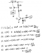
Thank you,I think the (R33 / R32) ratio is incorrect and I doubt that the PNP's VBE will be big enough to turn it on. I recommend a thought process similar to that in the attachment.
_
In Eq.no 3, Hope you are assuming a VCE(sat) of Q1 as 0.5V.
Thanks
@Mark Johnson,
I haven't read through this whole thread yet. Can you point me to the latest version and what PCB is available for ordering post?
Thx.
I haven't read through this whole thread yet. Can you point me to the latest version and what PCB is available for ordering post?
Thx.
- Home
- Amplifiers
- Power Supplies
- PCB: low voltage On-Off switch drives AC mains relay \ includes soft start .. H9KPXG