@ chiptech. I am sorry but I am unable to diagnose your problem. I hope Mark Johnson may chime in for you
@chiptech do you have jumper in momentaryposition?
According to datasheet you have maintained switch so momentary jumper shouldn't be populated.
According to datasheet you have maintained switch so momentary jumper shouldn't be populated.
Last edited:
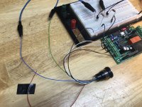
It seems to me that @Ripster has asked the right question: which is misbehaving, the PCB or the switch?
One way to find out is to temporarily substitute a known-good (tested with ohmmeter) toggle switch.
One way to find out is to temporarily substitute a known-good (tested with ohmmeter) toggle switch.
Turns out I did have the momentary option engaged. I have undone that.
I swapped in a newly built board and switch.
It all works.
I will be converting 3 more Pass amps. I will test the first board and switch in my next conversion to hopefully get some clarity.
Thanks again, as always, for all the help and encouragement.
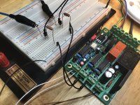
Mark, thanks for the H9KPXG. I covered new ground, from ordering the boards from a fab shop [still have 4 boards to share if anyone needs one. $8.00 all in] to chasing around the world sourcing parts {also have the MS32-200080.
It's a fun board to fill in and just looks cool.
And now I can turn these amps on/off without bending into a pretzel to reach around back.
I swapped in a newly built board and switch.
It all works.
I will be converting 3 more Pass amps. I will test the first board and switch in my next conversion to hopefully get some clarity.
Thanks again, as always, for all the help and encouragement.
Mark, thanks for the H9KPXG. I covered new ground, from ordering the boards from a fab shop [still have 4 boards to share if anyone needs one. $8.00 all in] to chasing around the world sourcing parts {also have the MS32-200080.
It's a fun board to fill in and just looks cool.
And now I can turn these amps on/off without bending into a pretzel to reach around back.
One way to find out is to temporarily substitute a known-good (tested with ohmmeter) toggle switch.
Or a just a piece of wire across switch terminals.
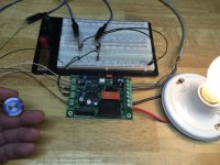
A friend of mine is looking for something to soft start a power strip in his sound room which has an early 70's, 50w/ch stereo receiver that he loves, and a couple other components plugged into it. I wonder if this would work well for that purpose? I'm thinking I could make a little box to put it in with an IEC inlet and a fuse holder. Other options could be something made with a couple of contactors and a timer relay.
I just repaired his receiver which was blowing fuses because of shorted rectifier diodes. Likely due to excessive inrush current.
I just repaired his receiver which was blowing fuses because of shorted rectifier diodes. Likely due to excessive inrush current.
For a 3-outlet power strip you'd need 3 of these PCBs, one PCB per outlet. Equipment plugged into outlet#1 will probably not be turned on at the exact same instant as equipment plugged into outlet#3. They require separate and independent soft start mechanisms. And don't forget that the on/off switch & pilot light LEDs are connected to this PCB. Putting 3 of these PCBs into a power strip means the power strip itself would have 3 on/off switches and 3 LEDs on its front panel. Probably not what anybody wants.
_
_
Last edited:
Thanks for replying.
My friend currently leaves all components powered on and switches on the power strip. Basically, a soft start would do the same job. I don't see a reason for needing more than one? Most collectors of old equipment do this because the power switches in old receivers fail from inrush current/ arcing. Especially the switches that are on the back on volume pots.
If I built something using AC contactors it would probably work the same way. Just to ramp up initial power on.
Last edited:
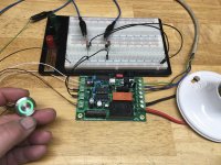
My amplifier previously had the two blue LED indicator lamps and now has a 19mm opening for an Anti-Vandal switch. My ambition is to have the switch ring lit green in "standby" mode and blue in the "on" mode with the two indicator lamps coming on as well, all powered by the H9KPXG.
I'm having a hard time finding a switch meeting my requirements:
Anti-Vandal
19mm
momentary
bi-color green/blue
common cathode
I've searched many manufacturer sites (Bulgin, E-Switch, etc.) but haven't come up with a solution yet.
I've also searched this thread and found an alternative wiring for using reverse bias diodes seen on many bi-color switches...that solution doesn't appeal to me. Audiobears bi-color solution had me excited but that switch is red/blue and 16mm.
Any Ideas would be appreciated
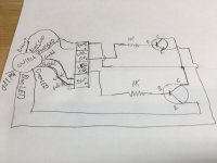
I finally figured out a solution this problem. I had bought a Bulgin capacitive switch with RGB LED's thinking it would be a plug in solution...it wasn't. After a lot of head scratching I eventually figured a way to make it work with the addition of just two NPN transistors and a couple resistors. The transistors are simply used as a switch to connect the LED cathode to ground. When either the "on" or "off" LED output of H9KPXG is hot, it in turn puts a current on the base of the transistor making the emitter and collector a closed circuit to ground. It seems simple to me now, but believe me, it took a ton of reading and experimenting for me to figure this out. I made a drawing of the circuit as best I could.
Attachments

Is there a more elegant way to accomplish what I’ve done with the two transistors? I don’t know much about micro controllers, but is that a possibility?
What is the true difference between this board and the Neurochrome 'intelligent soft start'?
I find that hard to believe that the NC has > 200J rating since it seems to be using very similar components. What gives?
Is it just a case of Mark giving a more conservative rating for his board or what? I don't understand the way the neurochrome board handles the turn on with the solid state device. They state the device is able to tolerate only a certain amount of cycles before blowing up. It doesn't sound very reassuring. 🙂
Compare the feature list of this board (post #1) to the feature list of the alternate board you're considering. I'd bet money they're not identical.
Read the posts in this thread from May-2020 and also from August-2020. They contain the information you need to figure out the answer to your question. There were only a couple dozen posts in each of those months, it won't take long.
Read the posts in this thread from May-2020 and also from August-2020. They contain the information you need to figure out the answer to your question. There were only a couple dozen posts in each of those months, it won't take long.
Thanks Mark,
Are you referring to your post #109 and the different 250J ICL? Is that the key difference that gives the higher rating to the whole board?
That's all I could find that seemed relevant.
Are you referring to your post #109 and the different 250J ICL? Is that the key difference that gives the higher rating to the whole board?
That's all I could find that seemed relevant.
The ICL disc is the only component with a Joule rating, and it is also the only component which determines the Joule rating of the entire assembled PCB.
If it's worth seven dollars to you, to own the very biggest Joule rating that (barely) fits on the PCB, then get a 250 Joule ICL disc. Massive overkill is, after all, a well respected and time honored goal of DIYers. Otherwise, stay with the 125 Joule disc and be happy. FYI the ICL disc which Nelson Pass recommends for all of his First Watt (200 VA transformer) designs here on diyAudio, is an Amphenol CL60, rated for a whopping 36 Joules. 125 Joules is 3.5x greater and 250 Joules is 7x greater. But perhaps bragging rights are worth the extra money, to some builders.
If it's worth seven dollars to you, to own the very biggest Joule rating that (barely) fits on the PCB, then get a 250 Joule ICL disc. Massive overkill is, after all, a well respected and time honored goal of DIYers. Otherwise, stay with the 125 Joule disc and be happy. FYI the ICL disc which Nelson Pass recommends for all of his First Watt (200 VA transformer) designs here on diyAudio, is an Amphenol CL60, rated for a whopping 36 Joules. 125 Joules is 3.5x greater and 250 Joules is 7x greater. But perhaps bragging rights are worth the extra money, to some builders.
Thanks Mark,
This would go in a different project. switching 2x600VA transformers and two beefy 75-0-75 capacitor banks. I haven't done the J calc but like you said, overbuild it's one of the DIYer goals.
I want to make sure and sleep on two mattresses for this one. 😉
This would go in a different project. switching 2x600VA transformers and two beefy 75-0-75 capacitor banks. I haven't done the J calc but like you said, overbuild it's one of the DIYer goals.
I want to make sure and sleep on two mattresses for this one. 😉
Actually, I have two banks of 12 x 6800uF + 2x 4700uF @ 75VDC. Based on that it looks like I am even short with 1 soft start per transformer! This is w/o factoring in the toroidal short at power on. This board may not do it.
Would anyone be able to comment on whether VO3063 is a suitable substitute for the MOC3063M.?
I have looked at various parameters but it is all way above my level I'm afraid.
Thanks in advance
I have looked at various parameters but it is all way above my level I'm afraid.
Thanks in advance
The CD4001BEE4 is not available for now, may i use the CD4001UBEE4 ? the only thing i see in the datasheet is that the propagation delay time is shorter. May be something else i did not see .
B = buffered --> steeper edge rates (risetime, falltime) on its outputs
UB = unbuffered --> more leisurely edge rates
Either will work well in this board; if you are nervous, solder in a DIP socket and only use the UB part until you are able to purchase a B part. Then swap it into the socket.
UB = unbuffered --> more leisurely edge rates
Either will work well in this board; if you are nervous, solder in a DIP socket and only use the UB part until you are able to purchase a B part. Then swap it into the socket.
- Home
- Amplifiers
- Power Supplies
- PCB: low voltage On-Off switch drives AC mains relay \ includes soft start .. H9KPXG