It doesn’t matter how small or big is the power supply, it will always have some inrush current to handle.
so, to answer to your question, taking out these components will let the board work as a delayed switch
but in this case you have to consider that inrush current, however small, will be handled only by the tiny relay contact
Of course there's always inrush, but it is so small that I'm not worrying of tripping the breaker or damaging the PSU. We're talking of 15VA transformer and minimal cap banks here... I just need all the convenience of this circuit without the inrush. On the other hand, I'll use fully completed boards for power amps.
Forget about my request... I'll thinker with it myself, it's a simple enough circuit anyways.
Do
Let's pretend that posts #257 and #261 began with the words "Dear membership of diyAudio" , namely, those questions were addressed to the entire community of Forum readers.
Would anyone like to reply to either or both of those requests?
Would anyone like to reply to either or both of those requests?
Let's pretend that posts #257 and #261 began with the words "Dear membership of diyAudio" , namely, those questions were addressed to the entire community of Forum readers.
Would anyone like to reply to either or both of those requests?
Mark:
You're right, and I apologize for dumping my question on you; you don't need to answer to anyone and this entire community has been incredibly helpful in my audio education.
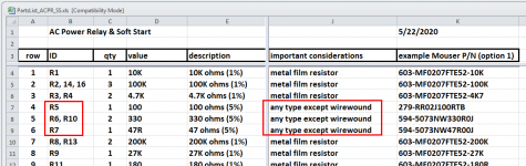
Can anyone explain to me why wirewound resistors are less suitable (or non-suitable) in certain applications, such as at R5 on the H9KPXG circuit?
Regards,
Scott
Q re C3
C3 (listed on the BOM as a Wima .022 uF) is on a 16 week back order at Mouser. I found a Wima cap in the same series with the same (or slightly smaller) dimensions but with a lower voltage rating (400 instead of 630 DC and 200 instead of 400 AC). MKS4G022202C00KSSD WIMA | Mouser
Would this be an acceptable substitute?
Thank you for any help anyone can give.
Jazzzman
This KEMET part should do the trick, jazzman. At least, the lead spacing is right.
https://www.mouser.ca/ProductDetail/KEMET/PHE450MK5220JR06?qs=WOIyg0mTyofQcmB5e6tc7Q==
https://www.mouser.ca/ProductDetail/KEMET/PHE450MK5220JR06?qs=WOIyg0mTyofQcmB5e6tc7Q==
On 120V mains I think the 200 VAC part will be okay. Probably the higher rated part is better for those who have 230 or 240V mains? The Rifa (PHE450) part suggested by kodabmx is fine although perhaps its full potential won’t be needed for this role.Would this be an acceptable substitute?
Thank you for any help anyone can give.
Jazzzman
Let's start with something 'simple'.That would be a great idea! I think you might find there are far fewer choices of relays with >15 ampere contacts, when you search for double-pole relays instead of the single-pole relay used in H9KPXG.
The new relay might turn out to be housed in a physically larger package, and the necessary coil current to activate it might be a lot higher. The extra current probably won't be a problem since the AC-to-DC converter has plenty of output. But, if not, then perhaps you could change the entire circuit to operate from 12V instead of 5V. The CD4000 logic family is rated for 12V (in fact, 15V!) and the low voltage switch is almost certainly rated for it.
I don't think I will include this in the H9KPXG, but please accept my encouragement to try out the idea yourself.
Would the TN2106 allow to drive 2 relays instead of 1? In that case it would only be necessary to add a relay/diode in parallel on the pcb without changing the other parts.
Let's pretend that posts #257 and #261 began with the words "Dear membership of diyAudio" , namely, those questions were addressed to the entire community of Forum readers.
Would anyone like to reply to either or both of those requests?
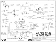
Ok, I've digged a little bit more the schematic and found the solution by my self to my question (post #257)
at first power on C8 is discharged and take some time to charge. While C8 reach it’s charge U5A have SW_ON (+) and DLY_BRIEF (-) (U3E and U3D)
U5A is a NOR gate so it will issue a LOW signal (TRIAC_B = Low)
Q3 will light the optocoupler (U4) and Triac let the main flow
Now, some time passed, C8 is at is nominal charge and U3E change it’s logic state and so do U5A issuing a HIGH signal (Triac_B = High)
Now, only now, Q3 and U4 will react, turning off the Triac
All this will happen in a very short time but it is sufficient to fire up my big donut
Is this critical ? I really don’t know but I think I will not mount C8 again…
Mark:
I'm in the midst of building my first H9KPXG board and have just discovered that the 100R 3W resistor in my inventory that I was going to use at R5 is a Vishay RS series wirewound. Your BOM warns against using wirewounds in that position. Can you explain why?
Regards,
Scott
Maybe I'm wrong but I believe that it is because wirewounds resistor have some characteristics inductance that are not suitable for the pourpose that R5 is intended for in this specific position
R5 and BR1 are parts of safety circuit Mark designed to save our lives...🙂
Maybe I'm wrong but I believe that it is because wirewounds resistor have some characteristics inductance that are not suitable for the pourpose that R5 is intended for in this specific position
R5 and BR1 are parts of safety circuit Mark designed to save our lives...🙂
Michele:
That's interesting and something I wouldn't have guessed. Unless someone says otherwise, I'll trust your response is correct. That changes things a little, and I now need to order some resistors.
Thank you!
Regards,
Scott
I believed that everyone who builds one of these boards, will need to order some or all of the components from a distributor. After all, who has a triac AND a 125 Joule inrush current limiter disc AND an AC-to-DC converter module with the right pinout AND the correct sized wire-to-board terminal blocks, sitting in their parts bin?? My answer: nobody. This means: absolutely every builder will order many or perhaps all of the line items on the Detailed Parts List.
Since you're going to be placing a parts order anyway, I may as well recommend that you order the least controversial, greatest safety, most tried and true components that I'm aware of. And, for the resistors which connect to the AC mains, those are non wirewound resistors. Just order them and use them and sleep soundly at night.
_
Attachments
When I turn it on with the mains inlet switch some current flows to the transformer and there are about 10v DC at the power supply output. This will slowly goes to zero while the capacitors discharge.
Unfortunately, what you are doing is exactly the opposite of what the AC mains relay & soft start board expects.
The board expects that you will leave the mains inlet switch ON at all times, and will turn the audio equipment on and off using the low voltage front panel switch.
The board contains an "always on" 5V DC power supply, carefully selected to meet international standards of ultra low standby power. And the circuit design assumes this 5V power supply is always on, namely, that it is always connected to the AC mains. But you are switching it off (and on) from the inlet switch. That was not forseen, indeed it was not even imagined, when I designed the circuit. Don't do that!
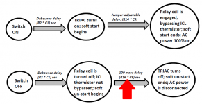
I don't recommend removing capacitor C8; it has an important function and that's why it's present on the circuit board. The state transition diagram from post #1 of this thread (copied below) shows why: C8 gives the soft unstart behavior that we want, to protect the relay contacts during shutdown. Removing C8 destroys the soft unstart, and thereby eliminates contact protection during shutdown. Don't do that.
If you are confident in your knowledge, and if you are brave, and if you really want to tinker around, you could replace C8 with a 1 microfarad capacitor to VDD instead of the existing 1 microfarad to VSS. You might as well use a nonpolar capacitor for the experiment, just so you don't have to worry about which plate of the capacitor is connected to which node. 1uF nonpolar capacitors are available in ceramic, film, and "bipolar electrolytic" types. A physically small cap with nice long leads would allow easy experimentation, and you'll want to have several of them so you can make several attempts.
_
Attachments
Mark, I don’t like to make something w/o trying to understand what I’m doing, this is the reason why i wrote post #257
I live in a home that have a home automation system. When nobody is in, the home enter into sleep mode and all non essential appliances (including my Hi-Fi stuff) are disconnected from mains.
Now I see that the answer to my question was already here, in post #1.
I appreciate a lot your suggestion and will change C8 to vdd
If doing a dual mono amp, just connect both transformers in parallel (in this case two 300VA dual secondary 36v) to the soft start board like you would one transformer?
Free PCBs
Due to a special at JLCPCB I received 5 extra PCB boards for just $2.00. They are green and were made to recommended specs: 1.6mm thick, FR4, ENIG with 2 oz. copper. As Christmas is coming I thought I would offer them to the first 5 people who PM me with their address. US only please, I don't want to deal with customs.
Due to a special at JLCPCB I received 5 extra PCB boards for just $2.00. They are green and were made to recommended specs: 1.6mm thick, FR4, ENIG with 2 oz. copper. As Christmas is coming I thought I would offer them to the first 5 people who PM me with their address. US only please, I don't want to deal with customs.

There's a much easier and effective way of activating a power relay.
Using a 4017 chip's outputs - along with a 555 timer.
Been done for years, and works very well.
Using a 4017 chip's outputs - along with a 555 timer.
Been done for years, and works very well.
- Home
- Amplifiers
- Power Supplies
- PCB: low voltage On-Off switch drives AC mains relay \ includes soft start .. H9KPXG