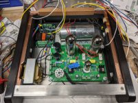
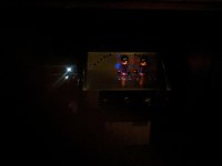
Sharing another completed project using Mark's soft start board. It is doing it's job in my recently completed Tubelab SSE. Makes life easier on the tubes set for a 2 sec delay along with the piece of mind that only 5V is running to the push button switch on the front. I think the blue led power on "accent lighting" it provides is perfect using the spec'd resistor. Of course now I need to do something about those retina abusive white leds on the components to the left.
I am sure I have been one of the needier builders so a big public thank you to Mark for his generosity in helping me out!
I am sure I have been one of the needier builders so a big public thank you to Mark for his generosity in helping me out!
Attachments

Lovely build, spiggs. Congratulations! I agree with you, that eerie blue glow from within is very appealing. Well done and good on ya.
Folks:
In case anyone in North America is looking for H9KPXG boards, my order has arrived and boards are now available. Please check the thread in the Swap Meet forum: https://www.diyaudio.com/forums/swa...g-lv-switch-soft-start-pcb-2.html#post6399543
Regards,
Scott
In case anyone in North America is looking for H9KPXG boards, my order has arrived and boards are now available. Please check the thread in the Swap Meet forum: https://www.diyaudio.com/forums/swa...g-lv-switch-soft-start-pcb-2.html#post6399543
Regards,
Scott

Hi all,
Got the PCBs today and assembled one board, tested and fully working! Thanks Mark for this super nice project!!
I have a question for you or anyone that could answer it... I plan on installing a Bulgin momentary switch with dual colour LED. Unfortunately, this requires reverse polarity for the second colour to light up. Anything possible with the current design to make this work without having to install relays or other ICs to do this properly?
Thanks
Do
> a Bulgin momentary switch with dual colour LED.
Bulgin has a very impressive catalog of many-many choices. Clue?
The first dual-LED I found looks like common-cathode which may be dead-simple in Mark's circuit?
https://www.diyaudio.com/forums/att...cludes-soft-start-h9kpxg-schematic_acprss-png
Bulgin has a very impressive catalog of many-many choices. Clue?
The first dual-LED I found looks like common-cathode which may be dead-simple in Mark's circuit?
https://www.diyaudio.com/forums/att...cludes-soft-start-h9kpxg-schematic_acprss-png
Attachments
Hi PRR,
Yeah, a three wire common cathode is ideal in this scenario but I already have those bulgin switches and it is a two wire which requires reverse polarity to light the second led.
For now I just connected a led directly on standby so I can see it through the chassis grill.
Thanks
Do
Yeah, a three wire common cathode is ideal in this scenario but I already have those bulgin switches and it is a two wire which requires reverse polarity to light the second led.
For now I just connected a led directly on standby so I can see it through the chassis grill.
Thanks
Do
Last edited:


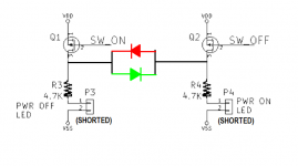
@pinnocchio --- if you are an extremely brave DIYer with excellent fabrication skills, you could consider soldering a couple of "bodge" wires to the upper (loopy) leads of resistors R3 and R4; and then connect those wires to a two-pin, bidirectional, bicolor LED. You'd need to devise a way to mechanically support those wires, because solder joints are notoriously fragile. This is certainly not a supported option, and I don't recommend it, and if you decide to do it anyway: you are completely on your own. So don't try it unless you are extremely brave.
_
_
Attachments

Thanks to the generosity of mcaronas who kindly sent
me a board I now have a working assembled pcb just need to wire it into an amp.
A big thank you to Mark for making these available.


me a board I now have a working assembled pcb just need to wire it into an amp.
A big thank you to Mark for making these available.
Congratulations on your success, Marra! Pleased to see you have chosen the 1 second delay option for your bypass.
Hi Mark,
If I want to use this circuit for powering a small current device like a preamplifier, I don't really need the TRIAC and Inrush, just the bypass relay. Looking at the schematics, can I omit the following parts :
Q3
U4
R6, R7, R10, R11, R16
T1
C3, C8
ICL1
Am I missing anything?
Thanks
Do
If I want to use this circuit for powering a small current device like a preamplifier, I don't really need the TRIAC and Inrush, just the bypass relay. Looking at the schematics, can I omit the following parts :
Q3
U4
R6, R7, R10, R11, R16
T1
C3, C8
ICL1
Am I missing anything?
Thanks
Do
Last edited:
Let's pretend that post #254 began with the words "Dear membership of diyAudio" , namely, it was addressed to the entire community of Forum readers.
Would anyone like to reply to this inquiry?
Would anyone like to reply to this inquiry?
Dear Mark,
I’ve a question for you 🙂
My board is connected to mains throught IEC inlet with double pole switch and I have a 400VA 18+18v transformer with DIYAudio Power supply v3 connected to it
When I turn it on with the mains inlet switch some current flows to the transformer and there are about 10v DC at the power supply output. This will slowly goes to zero while the capacitors discharge.
Besides this the board work fine.
I thought that this was due to the Triac snubber leakage, but I remove the snubber and it still the same
I’ve also tried with a snubberless triac (BTA16-600SWRG) but nothing changed
It seems that there is a transient probably due to optocoupler triggering the triac gate at power on
Is this a normal behavior?
Might be better to mark-up a schematic instead of a detailed text question. It has taken me 20 minutes to find the schematic, find the many SMALL parts listed, and mark them out. What is this, $5 of parts?
Hi PRR,
It’s not a question of cost, I don’t really care about the cost. It’s just of optimizing for the need. I’ve got some PCBs assembled for amplifiers and some for preamps. No need for inrush in the later case.
Do
electronic blasphemy/heresy
Since I am not qualified to completely understand what the effect of leaving the parts out, I ask the question a different way.
What is the affect of putting the board in as designed. And that is what I care about because I have a DCG3 pre and that is what I did. It seems to work great.
If there is a downside, that is what I would like to know about.
Not trying to dodge the original question. Different strokes for different folks.
I hope my approach doesn't make me a jerk to the electronic gurus.😱
I put the board in every DIY box I turn on.
Don
Let's pretend that post #254 began with the words "Dear membership of diyAudio" , namely, it was addressed to the entire community of Forum readers.
Would anyone like to reply to this inquiry?
Since I am not qualified to completely understand what the effect of leaving the parts out, I ask the question a different way.
What is the affect of putting the board in as designed. And that is what I care about because I have a DCG3 pre and that is what I did. It seems to work great.
If there is a downside, that is what I would like to know about.
Not trying to dodge the original question. Different strokes for different folks.
I hope my approach doesn't make me a jerk to the electronic gurus.😱
I put the board in every DIY box I turn on.
Don
If I want to use this circuit for powering a small current device like a preamplifier, I don't really need the TRIAC and Inrush, just the bypass relay.
It doesn’t matter how small or big is the power supply, it will always have some inrush current to handle.
so, to answer to your question, taking out these components will let the board work as a delayed switch
but in this case you have to consider that inrush current, however small, will be handled only by the tiny relay contact
Mark:
I'm in the midst of building my first H9KPXG board and have just discovered that the 100R 3W resistor in my inventory that I was going to use at R5 is a Vishay RS series wirewound. Your BOM warns against using wirewounds in that position. Can you explain why?
Regards,
Scott
I'm in the midst of building my first H9KPXG board and have just discovered that the 100R 3W resistor in my inventory that I was going to use at R5 is a Vishay RS series wirewound. Your BOM warns against using wirewounds in that position. Can you explain why?
Regards,
Scott
- Home
- Amplifiers
- Power Supplies
- PCB: low voltage On-Off switch drives AC mains relay \ includes soft start .. H9KPXG