They didn't seem to have to scale the 2x Rs and 2x Cs when switching from 40 - 60dB here:
https://www.analog.com/media/en/technical-documentation/data-sheets/lt1115fa.pdf
That's the TI implementation of T2, T3 and T4 but with the 499 ohm "tail" put there to trim-up the total feedback R in order to make 40dB. That's my yellow R. IOW, take the TI circuit attachment, keep the 127 ohm (or 120 or 100 ohm) and size the yellow for 45dB. Yellow becomes large so can that be done w/o screwing with the TCs? That's all.
They are switching R4. You either change R4 or scale the impedance of the rest. They made C4 so large they don't have to switch that.
I don't know exactly what the 499 ohm is for. The datasheet says: "The part is not generally applicable for unity gain followers or inverters" on page 7, so it may just be for stability, but there are other application circuits with a capacitor straight from the output to the negative input. Very vague.
Noise-wise, the LT1115, LT1028 and LT1128 are the very worst op-amps for MM, by the way.

Noise-wise, the LT1115, LT1028 and LT1128 are the very worst op-amps for MM, by the way.
Yes. Below the measurement of noise with Shure M35X cartridge. It is measured with linear gain +30dB and noise is referred to input. 47 kohm load. NE5534A is still the best talking about bipolar input opamps, but a bit worse than OPA627. Repetition is the mother of learning 😉.

Do you happen to know how the NE5532A performs compared to the NE5534A?
I know that at 1 kHz, both its equivalent input noise voltage and current specs are clearly worse than those of the NE5534A, but looking at the 30 Hz spec and the input bias current, I suspect it is still largely 1/f noise current at 1 kHz. If its noise current drops to √(2qIB) ~= 0.2532 pA/√Hz at higher frequencies, its total RIAA- and A-weighted noise should only barely be worse than that of the NE5534A for a 500 mH cartridge.
I know that at 1 kHz, both its equivalent input noise voltage and current specs are clearly worse than those of the NE5534A, but looking at the 30 Hz spec and the input bias current, I suspect it is still largely 1/f noise current at 1 kHz. If its noise current drops to √(2qIB) ~= 0.2532 pA/√Hz at higher frequencies, its total RIAA- and A-weighted noise should only barely be worse than that of the NE5534A for a 500 mH cartridge.
You've hit the nail right on the head.Repetition is the mother of learning 😉.
Repeat and repeat endlessly until you can do it in your sleep.
I don't know either today. Before I thought I calculated a DC gain boost with the 499R in-series with the EQ Rs and Cs vs. not. So you are saying that a resistor in series with the RIAA elements will not simply increase the (Rx + Ry / Rz) + 1 gain to x1770 DC gain. So that's that. No higher gain version for the TI circuit without EQ parts changes. Just needed to pass it by the Expert. Thank you sir.I don't know exactly what the 499 ohm is for. The datasheet says: "The part is not generally applicable for unity gain followers or inverters" on page 7, so it may just be for stability, but there are other application circuits with a capacitor straight from the output to the negative input. Very vague.
PS - Was not considering the LT parts. The schemo was just an example.
Last edited:
Marvel, Have yow resolved the R8 and R9 changes for a 627 op amp in your latest implementation, post 396?Except for R8 and R9, nothing changed. Mind you, a slower op-amp such as an OPA627 would need a somewhat larger correction (presumably around -400 ohm rather than -100 ohm, but I haven't checked that).
Regarding your question about the circuit of post #396, https://www.diyaudio.com/community/...split-from-opa1656-thread.377331/post-7940730 , suggested values with an OPA627 instead of an OPA1656:
Second-order: R8 = 34.8 kΩ, R9 = 0 Ω
Third-order: R8 = 19.6 kΩ, R9 = 15 kΩ
Second-order: R8 = 34.8 kΩ, R9 = 0 Ω
Third-order: R8 = 19.6 kΩ, R9 = 15 kΩ
I think he confused your abilities with your name! 🙂
//
//
A belated Thank You Marcel! Don't know why but I expected a larger diff in the R values.Regarding your question about the circuit of post #396, https://www.diyaudio.com/community/...split-from-opa1656-thread.377331/post-7940730 , suggested values with an OPA627 instead of an OPA1656:
Second-order: R8 = 34.8 kΩ, R9 = 0 Ω
Third-order: R8 = 19.6 kΩ, R9 = 15 kΩ
I see that the 627 3rd order R8+R9 sum is ~ 1.4% different from the 1656 3rd order R8+R9 sum. Would I risk spinning-up the gods of perfection if I just used the 1656 values in the 627 application..? And then ran far far away....
No, that should also work fine.
In fact, I'm not even sure that the values I recommended are an improvement. They shift the second RIAA pole closer to its ideal position, but at the expense of a less accurate RIAA zero. Basically I'm just smearing out the 0.23 dB error you get due to finite gain-bandwidth product over a wider frequency range.
In fact, I'm not even sure that the values I recommended are an improvement. They shift the second RIAA pole closer to its ideal position, but at the expense of a less accurate RIAA zero. Basically I'm just smearing out the 0.23 dB error you get due to finite gain-bandwidth product over a wider frequency range.
Last edited:
From #287: What about a straight-in, active 2nd order S-F subsonic filter with 5-6dB gain up-front of my TI RIAA EQ with standard 40dB gain. No cart buffer. So, everything in-band from the MM cart is boosted by 5-6dB while the freqs below say 16 are being attenuated by 12dB. Is that stupid vs. putting the gain in the EQ itself with 0dB gain in the preceding non-buffered S-K (i.e. 2-stage)? I'm still musing about adding 5-6dB gain + sub-sonic filtering + a low op-amp count. I can get two out three with my present 3rd order 0db filter gain setup if I lower the EQ section's gain R to say 72R and raise the cap to say 220uF Nichicon Muse - but that still takes three op-amps b/c of the cart buffer.I think so, but with a noise penalty.
BTW, I began some assembly of the Marcel Total Preamp yesterday. The board I chose is pretty crowded. Not finished with power supply rails or bypass. The R-C-R input network may have to go off-board near the RCAs. Those 2.2uF MKS2 are big. Right now they're onboard. We'll see.
Attachments
If you were to replace the RC parallel networks in the schematic of post #287 with just a resistor with a value about equal to R3, with R3 << R2, you would get at least about the same noise penalty as with the circuit of post #287.
I'm not sure if you could reduce the noise penalty by connecting R2 between the times-two amplifier output (rather than the op-amp's negative input) and the point where the two capacitors C1 and C2 are connected to each other. You get a negative damping term that you have to correct for by making R2 larger (which reduces its thermal noise current), but you also get a negative conductance term due to R2 then, so R1 then has to be smaller than the usual 47 kohm (which increases its thermal noise current).
I'm not sure if you could reduce the noise penalty by connecting R2 between the times-two amplifier output (rather than the op-amp's negative input) and the point where the two capacitors C1 and C2 are connected to each other. You get a negative damping term that you have to correct for by making R2 larger (which reduces its thermal noise current), but you also get a negative conductance term due to R2 then, so R1 then has to be smaller than the usual 47 kohm (which increases its thermal noise current).
Lost me right there. Sorry that I don't speak your math language.If you were to replace the RC parallel networks in the schematic of post #287 with just a resistor with a value about equal to R3, with R3 << R2, you would get at least about the same noise penalty as with the circuit of post #287.
Let me rephrase it in schematics then:

The upper schematic comes straight from post #287. I've shown there with a couple of noise transformations that it is not a very good circuit noise-wise, mostly because of the thermal noise current that R2 injects into the signal source.
The second schematic has the exact same issue.
Yesterday evening I was a bit too tired to work out the third solution, but it actually gets worse. This circuit also has 47 kohm input impedance at high frequencies (47.6666... kohm to be precise), but it injects more thermal noise current than the others.
I've also looked at obtaining the signal for R2 from a tap on R3 (not drawn), but that doesn't help much either.
Last edited:
Thank you sir.
So firstly are you thinking that an a) up-front active filter w/ 6dB gain => RIAA 40dB is preferable to; b) up-front active filter => RIAA 46dB? IOW if the added gain is incorporated downstream of the filter does that hurt or help with noise? And how much noise..? What magnitude and spectrum? Is it truly perceivable or not near enough to zero?
Also in the first example doesn't R2 see a wildly frequency dependent source impedance at the top of R3 plus its large cap to ground.?
I've also considered the attached 2-stage solution (i.e. takes care of the Low-Z drive for the S-K) which I thought later was a bad idea.
Attachments
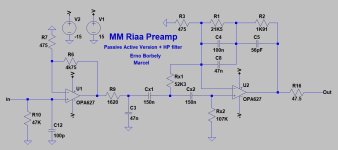
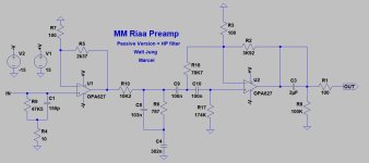
In this case wouldn't it be better to go for the active and passive preamps I had proposed originally, and which Marcel added the HP filter to? He also modified them to use without DC servos.
Attachments
- Home
- Source & Line
- Analogue Source
- OPA1656 Phono Preamp: Split from OPA1656 thread