You are killin' me Marvel. Stop it. Just stop and be happy with imperfection. Do something else with your precious time on Earth. What do you do for fun, relaxation, satisfaction, peace...The big disadvantage of my amplifier with subsonic filter is that I haven't found an accurate way to calculate the component values, so I had to resort to approximate calculations and tweaking with a pole-zero extraction program. That's quite unsatisfactory, as far as I'm concerned.
I myself don't have a good answer to that.

Please tell me how should I connect this inductor, because I tried several options at the input with no results to the curve.
In the schematic of post #416, just replace C2 with a series connection of C2 and an ideal inductor with value {Ls}. Then set parameter Ls to 0 or to some very small value such as 1E-9 when simulating the frequency response and to 0.5 when simulating noise.
(The reason for not taking into account the inductance when simulating the frequency response is that the cartridge manufacturer is supposed to take care of that. That is, the cartridge is supposed to be designed such that its mechanical transfer and the interaction of its inductance with its recommended load together result in the correct response from the record to the input voltage of the phono preamplifier.)
Just stop and be happy with imperfection. Do something else with your precious time on Earth. What do you do for fun, relaxation, satisfaction, peace...
Like to spend more time with a precious wife... or a precious girl friend your wife doesn't know about...
Can someone correct my asc file and add the inductor as explained?In the schematic of post #416, just replace C2 with a series connection of C2 and an ideal inductor with value {Ls}. Then set parameter Ls to 0 or to some very small value such as 1E-9 when simulating the frequency response and to 0.5 when simulating noise.
(The reason for not taking into account the inductance when simulating the frequency response is that the cartridge manufacturer is supposed to take care of that. That is, the cartridge is supposed to be designed such that its mechanical transfer and the interaction of its inductance with its recommended load together result in the correct response from the record to the input voltage of the phono preamplifier.)
I dunno. You may not have rugs or carpeting. You may use bookshelf speakers. You may not have two beefy power amps driving the mains and three subs. I'm not really certain about touching the tonearm finger lift b/c my TT is a fully automatic linear tracker so I never touch the tonearm. I would never own a pivot arm TT. And I would bet that your TT does not have a mute-shorting switch or it's a good, clean one. I never had a POP-THWUMP in 50 years of audio until the 1656 came along AND I built something around it.So you will have a system shielding, wiring and grounding issue. I do not experience any pops from speakers even after human ESD discharge through the tonearm, without turning volume down.
Marvel, did you mistakenly pass over this post?
https://www.analog.com/media/en/training-seminars/design-handbooks/Op-Amp-Applications/Section6.pdf
Starting pg 6.11 Jung goes through the basics of RIAA EQ, different topologies and whatnot then on pg 6.17 introduces a new external element to the "N" feedback network called R4. R3 is still the gain R and the Rs and Cs still perform the EQ but the new R4 and the old R3 (albeit changed in value from previous example) divide the voltage seen at -IN by five. In this case (pg 6.22) it's a MC cart design where a 5x opamp is needed thus assuring a min Av of x5 and the lifting the mid-band gain from 40 to 45dB. Now I don't understand how a 5x boost in gain equates to a 5dB increase. I am missing something for sure.
But, the question is can this trick be applied to the TI quasi-Lipshitz's RIAA feedback network shown with the OPA1656 on pg 19 of the datasheet? See attached example.
Comes from here:I don't understand what you mean. R4 in post #253 could be increased to get more gain.
https://www.analog.com/media/en/training-seminars/design-handbooks/Op-Amp-Applications/Section6.pdf
Starting pg 6.11 Jung goes through the basics of RIAA EQ, different topologies and whatnot then on pg 6.17 introduces a new external element to the "N" feedback network called R4. R3 is still the gain R and the Rs and Cs still perform the EQ but the new R4 and the old R3 (albeit changed in value from previous example) divide the voltage seen at -IN by five. In this case (pg 6.22) it's a MC cart design where a 5x opamp is needed thus assuring a min Av of x5 and the lifting the mid-band gain from 40 to 45dB. Now I don't understand how a 5x boost in gain equates to a 5dB increase. I am missing something for sure.
But, the question is can this trick be applied to the TI quasi-Lipshitz's RIAA feedback network shown with the OPA1656 on pg 19 of the datasheet? See attached example.
Attachments
I have carpets, large 3-way speakers and 2 x 300W amplifier. All of this is unimportant. If you still speak about this implementation of yours:I dunno. You may not have rugs or carpeting. You may use bookshelf speakers. You may not have two beefy power amps driving the mains and three subs. I'm not really certain about touching the tonearm finger lift b/c my TT is a fully automatic linear tracker so I never touch the tonearm. I would never own a pivot arm TT. And I would bet that your TT does not have a mute-shorting switch or it's a good, clean one. I never had a POP-THWUMP in 50 years of audio until the 1656 came along AND I built something around it.
Then it would be a miracle if you did not have troubles.
Comes from here:
https://www.analog.com/media/en/training-seminars/design-handbooks/Op-Amp-Applications/Section6.pdf
Starting pg 6.11 Jung goes through the basics of RIAA EQ, different topologies and whatnot then on pg 6.17 introduces a new external element to the "N" feedback network called R4. R3 is still the gain R and the Rs and Cs still perform the EQ but the new R4 and the old R3 (albeit changed in value from previous example) divide the voltage seen at -IN by five. In this case (pg 6.22) it's a MC cart design where a 5x opamp is needed thus assuring a min Av of x5 and the lifting the mid-band gain from 40 to 45dB. Now I don't understand how a 5x boost in gain equates to a 5dB increase. I am missing something for sure.
But, the question is can this trick be applied to the TI quasi-Lipshitz's RIAA feedback network shown with the OPA1656 on pg 19 of the datasheet? See attached example.
R3 in figure 6-15 is smaller than R3 in figure 6-11, hence the higher gain at 1 kHz. It should be roughly 100/56.2 times as high, which is about 5 dB.
For frequencies in the megahertz range, the feedback network of figure 6-11 does not attenuate, while that of figure 6-15 attenuates 1 + 220/56.2 times, which is almost five times. Hence, figure 6-15 should be stable with a gain of five op-amp, and its gain far above the audio band is five times rather than 1 time, bringing the undesired zero five times closer. The undesired zero is corrected for with an RC filter after the op-amp.
Why do you want to apply this to the unity-gain-stable OPA1656?
Last edited:
Figure 6-15 schematic was published in the LT1115 Spec Sheet, right in the first page, in MM-MC versions. It was probably designed by Walt Jung himself.
https://www.analog.com/media/en/technical-documentation/data-sheets/lt1115fa.pdf
Later on Adcom used a different version of this RIAA on their preamp GFP-565, changing the LT1115 for an LT1028.
This preamp was modified by Gary Galo in a 4-part project published in AudioXpress magazine, in 2003 and 2004. I'm not sure if I can upload here a pdf of the last part, involving specifically the update of the RIAA preamp. Do tell me if it's allowed.
Galo's version uses the AD745 biFET opamp on 1st stage, and adding a DC servo designed by WJ.
My implementation for this preamp, instead of a prototype pcb, would be to use an existent and rather similar electronic layout, changing and adding the necessary passive parts.I have carpets, large 3-way speakers and 2 x 300W amplifier. All of this is unimportant. If you still speak about this implementation of yours:
View attachment 1428005
Then it would be a miracle if you did not have troubles.
I looked around what Aliexpress has available that could be adapted, and found this.
https://www.aliexpress.com/item/100...WoD29Zhw&utparam-url=scene:search|query_from:
What do you think?
I was asking whether the spitting of the feedback resistor trick could be utilized (in my case) in the quasi-Lipshitz MM topology (as shown in the 1656 and 1641/42 datasheets) to boost the gain in what I have now to say 45-46dB vs. 40dbB. The R3 in 6-15 is too small so could R3 and the new R4 be scaled-up to provide the gain boost + allow for a reasonably-sized C4 as in the TI attachment (i.e. R3 =/> 127 ohm)? Then I'd have what I had (OPA627) but with the added gain for my gain-poor system. And of course I'll build yours as well. Note that I innocently call the TI circuit quasi-Lipshitz b/c Lipshitz, a mathematician, published a long and math-dense paper on doing RIAA the right way - the design of which looked like the TI implementation but only realized the 3180 and 318 TCs in the feedback where the 75 was left to a LPF on the output. The TI version realizes all three in the feedback. FWIW...Why do you want to apply this to the unity-gain-stable OPA1656?
In the attachment of post #283, https://www.diyaudio.com/community/...split-from-opa1656-thread.377331/post-7934001 , adding the yellow resistor does practically nothing for the gain at 1 kHz. The gain at frequencies far above the audio band increases, making the circuit suitable for gain-of-three or gain-of-five stable op-amps when the resistance of the yellow resistor is at least twice or at least four times, respectively, that of R4.
Last edited:
If you want to increase the gain at 1 kHz, you either have to reduce R4 and increase C4, or scale up the impedances of R2, R3, C2 and C3, all by the same factor (resistors larger, capacitors smaller). That is, this is approximately correct, if you care about the last 0.1 dB, you have to do a more complicated calculation.
I kinda like that idea. This one might be closer to Marvel's topology:My implementation for this preamp, instead of a prototype pcb, would be to use an existent and rather similar electronic layout, changing and adding the necessary passive parts.
I looked around what Aliexpress has available that could be adapted, and found this.
https://www.aliexpress.com/item/100...WoD29Zhw&utparam-url=scene:search|query_from:
What do you think?
https://www.aliexpress.us/item/3256...mHLKH9ZV&utparam-url=scene:search|query_from:
And there others using 2x singles and 2x singles per channel for active passive versions. Interesting place!
They didn't seem to have to scale the 2x Rs and 2x Cs when switching from 40 - 60dB here:If you want to increase the gain at 1 kHz, you either have to reduce R4 and increase C4, or scale up the impedances of R2, R3, C2 and C3, all by the same factor (resistors larger, capacitors smaller). That is, this is approximately correct, if you care about the last 0.1 dB, you have to do a more complicated calculation.
https://www.analog.com/media/en/technical-documentation/data-sheets/lt1115fa.pdf
That's the TI implementation of T2, T3 and T4 but with the 499 ohm "tail" put there to trim-up the total feedback R in order to make 40dB. That's my yellow R. IOW, take the TI circuit attachment, keep the 127 ohm (or 120 or 100 ohm) and size the yellow for 45dB. Yellow becomes large so can that be done w/o screwing with the TCs? That's all.
Pavel Macura's Openamp1 is another example of this RIAA implementation, this time also using a biFET, an OPA627.
His choice of gain is just 40dB, which is also the gain used by Gary Galo in his Adcom mod.
His choice of gain is just 40dB, which is also the gain used by Gary Galo in his Adcom mod.
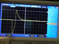
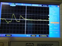
Isn't that a beaut! You should see the flip-side. That was pass #1 using 1% P-styrene caps from Nebraska Surplus back in 2021. Checked it out thoroughly as best I could with function gen and scope and a list of RIAA freq specs. I got some flack here about the "build" and improvements needed for parasitic this and that, grounding and so on so I redid it. I had no troubles with #1 until my first LP play when I did run the volume down for the first drop, then turned it up and it sounded clean - no misbehavior at all so I walked away thinking I'll listen from my home office while it's breaking in. The first side finished and then came the attached "OPA1656 lift ampitude" when the TT's slide switch closed as it lifted thus shorting the + and- cart outputs and pretty much bottomed my system. As I was running to the system the arm was traversing back to its rest but it was faster than I so there was another Wham-bang as the slide switch opened thus un-shorting the cart outputs as it dropped onto its rest where you see the 1656's behavior in the 2nd pic. So let's not talk about EMI/RFI influences anymore. 😉Then it would be a miracle if you did not have troubles.
Attachments
Thanks for that carlmart! I must suggest a slight correction though. The OPA627/637 is part of the BB diFET or DiFET or whatever, family - differentiating from BiFETs.Pavel Macura's Openamp1 is another example of this RIAA implementation, this time also using a biFET, an OPA627
- Home
- Source & Line
- Analogue Source
- OPA1656 Phono Preamp: Split from OPA1656 thread