LTspice sims do a fine job of exposing RIAA conformance anomalies and if you are using 1% components, the spread is significant if you do a Monte Carlo analysis. That said, the native response spread of a vinyl recording and playback chain is greater.
I have never designed and built an all active RIAA phono preamp that did not require a LPF on the output (I call this a ‘post secondary filter’), usually with a corner frequency of between 50 and 150 kHz to get the conformance to better than about 0.1 dB in the top octave. This filter does affect the shape of the midband response.
With all active, there’s a lot of ‘moving parts’ and what seem like innocuous little changes or tweaks often have a bigger impact in response than one would expect.
Thank goodness for circuit simulators!

I try to keep C2 as large as possible given the desired time constant and using only E6 values for the capacitors. The larger C2, the smaller the total thermal noise √(kT/C2) voltage drop across it. It doesn't really matter much, as most of this noise is subsonic or at very low frequencies that are barely audible. Another small advantage is less sensitivity to hum current injected at the positive op-amp input than with a smaller capacitor and bigger resistor.
LTspice sims do a fine job of exposing RIAA conformance anomalies and if you are using 1% components, the spread is significant if you do a Monte Carlo analysis. That said, the native response spread of a vinyl recording and playback chain is greater.
I have never designed and built an all active RIAA phono preamp that did not require a LPF on the output (I call this a ‘post secondary filter’), usually with a corner frequency of between 50 and 150 kHz to get the conformance to better than about 0.1 dB in the top octave. This filter does affect the shape of the midband response.
With all active, there’s a lot of ‘moving parts’ and what seem like innocuous little changes or tweaks often have a bigger impact in response than one would expect.
The big disadvantage of my amplifier with subsonic filter is that I haven't found an accurate way to calculate the component values, so I had to resort to approximate calculations and tweaking with a pole-zero extraction program. That's quite unsatisfactory, as far as I'm concerned.
Thank goodness for circuit simulators!
After spending several decades sitting behind a simulator each working day waiting for simulation results and trying to decipher cryptic error messages, I'm totally and utterly fed up with the damn things. My work is 1 % designing electronics and 99 % fighting with the damn computer.
If you do RIAA conformance plots, it is a good idea to extend the analysis to >> audio band - say to 500 kHz.
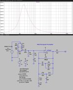
Here is a reasonably respectable all-active opamp based phono amp covering just the audio band and without the secondary LPF. Its within 0.2dB.

Here's the extended response

And here is the same preamp with the secondary LPF in place. Ideally, the response should be tight in the audio band and drop off at 20dB/decade at HF beyond the audio band - in other words, having tight conformance over the audio band but out-of-band peaking or other response anomalies should be avoided.

The magnitude of the mid-band gain has a big impact on the response in the top octave of the audio band - which is exactly what Marcel has mentioned. If the gain is lowered, the upward lift in the response beyond 20 kHz is greater, and the requirement for the secondary LPF filter even more important. I usually set my RIAA EQ amps to 35-40 dB gain. I would also add that I am probably too pathological about getting the conformance to <0.1 dB - but given the vagaries of the recording and playback chain responses, this is overkill.
[clarification: none of these plots considers the cart<>load<>preamp interface response - these plots are just for the EQ response and the preamp was fed with a lo Z source]
Here is a reasonably respectable all-active opamp based phono amp covering just the audio band and without the secondary LPF. Its within 0.2dB.
Here's the extended response
And here is the same preamp with the secondary LPF in place. Ideally, the response should be tight in the audio band and drop off at 20dB/decade at HF beyond the audio band - in other words, having tight conformance over the audio band but out-of-band peaking or other response anomalies should be avoided.
The magnitude of the mid-band gain has a big impact on the response in the top octave of the audio band - which is exactly what Marcel has mentioned. If the gain is lowered, the upward lift in the response beyond 20 kHz is greater, and the requirement for the secondary LPF filter even more important. I usually set my RIAA EQ amps to 35-40 dB gain. I would also add that I am probably too pathological about getting the conformance to <0.1 dB - but given the vagaries of the recording and playback chain responses, this is overkill.
[clarification: none of these plots considers the cart<>load<>preamp interface response - these plots are just for the EQ response and the preamp was fed with a lo Z source]
Last edited:
Luckily RIAA EQ amps are simple things for simulators Marcel 🙂The big disadvantage of my amplifier with subsonic filter is that I haven't found an accurate way to calculate the component values, so I had to resort to approximate calculations and tweaking with a pole-zero extraction program. That's quite unsatisfactory, as far as I'm concerned.
After spending several decades sitting behind a simulator each working day waiting for simulation results and trying to decipher cryptic error messages, I'm totally and utterly fed up with the damn things. My work is 1 % designing electronics and 99 % fighting with the damn computer.
A real phono system's subsonic response is (almost) dominated by the mechanical resonance of arm effective mass x cartridge cantilever suspension compliance, and its high frequency response by the ETM x vinyl compliance resonance. I suppose these could be re-purposed with Linkwitz transforms, but in both cases some damage is already done. At low frequencies by time modulation (FM) and at high frequencies by geometric errors and elastic deformation. Still fun though.
All good fortune,
Chris
All good fortune,
Chris
If you do RIAA conformance plots, it is a good idea to extend the analysis to >> audio band - say to 500 kHz.
Ideally, the response should be tight in the audio band and drop off at 20dB/decade at HF beyond the audio band - in other words, having tight conformance over the audio band but out-of-band peaking or other response anomalies should be avoided.
Why? All that ultrasonic rise means is that the gain levels off at 1 while the theoretical reverse RIAA correction keeps rising indefinitely. In real life, even though the rumours about the Neumann pole are nonsense, the record cutting machine will roll off somewhere, probably at a higher-than-first-order rate and starting from a frequency below 100 kHz. On top of that, there is the roll-off of the cartridge and the damping of the internal wall (assuming it are the bats hibernating in your cavity wall you are concerned about).
Well, some conclusions about previous preconceived ideas I had.
1) Single stage RIAA preamps seem to be able to sound good too, so they should enter on my comparison between RIAA preamps.
2) Simmed the high version of Marcel's latest proposed RIAA. Seems to be only interesting for low output MMs. No change in low FR decay per octave. Adding more parts doesn't seem justified.
3) Found some 6.8uF poly caps on AE (which they say are Wima).
https://www.aliexpress.com/item/100...drciefUu&utparam-url=scene:search|query_from:
Will try to get polystyrene for the other caps. There's a cheap supplier in the USA which stocks 1% and 2% styrenes and polypropylenes.
2) Has anyone simulated these circuits for noise response? I get weird humped noise curve: is that supposed to be so?
Posting #327.2) Has anyone simulated these circuits for noise response? I get weird humped noise curve: is that supposed to be so?
The hump was explained to you.
Hans
The input signal is bandwidth limited, but if you have a nasty peaky response preamplifier above 20k it will affect the in- band response. So, nice and flat in-band response that rolls off gently at 20 dB/decade at HF so it doesn’t affect the in-band response.Why? All that ultrasonic rise means is that the gain levels off at 1 while the theoretical reverse RIAA correction keeps rising indefinitely. In real life, even though the rumours about the Neumann pole are nonsense, the record cutting machine will roll off somewhere, probably at a higher-than-first-order rate and starting from a frequency below 100 kHz. On top of that, there is the roll-off of the cartridge and the damping of the internal wall (assuming it are the bats hibernating in your cavity wall you are concerned about).
(Agree that the Neumann thing is absolute nonsense and that the encoded signal is in any event bandwidth limited).
2) Simmed the high version of Marcel's latest proposed RIAA. Seems to be only interesting for low output MMs. No change in low FR decay per octave. Adding more parts doesn't seem justified.
The only reason to go for higher gain is that JRA wants more gain. Otherwise the high gain version of post #396, https://www.diyaudio.com/community/...split-from-opa1656-thread.377331/post-7940730 , is pretty similar to the circuit of post #248, https://www.diyaudio.com/community/...split-from-opa1656-thread.377331/post-7927613 , although I changed some minor details.
2) Has anyone simulated these circuits for noise response? I get weird humped noise curve: is that supposed to be so?
Hard to tell when you don't show what your "weird humped noise curve" looks like. The noise density plots should certainly be far from flat.
The equivalent input noise density should be sort of bathtub shaped due to the source impedance that rises with frequency, the 1/f noise and the coupling capacitor. The equivalent output noise density should roll off at high frequencies due to the RIAA correction and at low frequencies due to the decreasing source impedance and the subsonic filter.
Last edited:
It looks a bit weird due to the unrealistic non-inductive source impedance. You get roll-off below 16 Hz due to the subsonic filtering and above 16 Hz due to the decreasing impedance of the coupling capacitor and due to the RIAA correction. With 500 mH or so of inductance, the increasing source impedance more or less compensates for the RIAA roll-off over a wide frequency range.
Nebraska Surplus. Have bought from them before.Will try to get polystyrene for the other caps. There's a cheap supplier in the USA which stocks 1% and 2% styrenes and polypropylenes.
https://www.surplussales.com/categories/1634-capacitors-index/
Please tell me how should I connect this inductor, because I tried several options at the input with no results to the curve.It looks a bit weird due to the unrealistic non-inductive source impedance. You get roll-off below 16 Hz due to the subsonic filtering and above 16 Hz due to the decreasing impedance of the coupling capacitor and due to the RIAA correction. With 500 mH or so of inductance, the increasing source impedance more or less compensates for the RIAA roll-off over a wide frequency range.
Roger that Sir Marvel, Mouser:4) Any kind of fairly accurate film capacitor, definitely no class 2 ceramic capacitor. If I were building it, I would probably choose
https://www.reichelt.de/de/de/shop/produkt/mks2_pet-kondensator_6_8_f_5_50_vdc_rm_5-31931
because they take only little board area and you probably can't get much with less than 5 % tolerance anyway unless you are willing to pay a fortune.
https://www.mouser.com/datasheet/2/440/e_WIMA_MKS_2-1139871.pdf
- Home
- Source & Line
- Analogue Source
- OPA1656 Phono Preamp: Split from OPA1656 thread