OK, so it all seems to indicate that there is capacitive crosstalk from the left channel to the input of the right channel.
Possible receiving parts: R13, C2, R6, R3, C4, right-channel positive op-amp input, all wiring and copper islands and the connector that are connected to either side of C2.
Possible transmitting parts: anything connected to a left-channel node with a signal on it, probably an amplified signal:
Left-channel op-amp output, R40, R70, R80, R90, C60, C50 (side that is not connected to the negative op-amp input), R110, and their connecting wires, connector and copper islands.
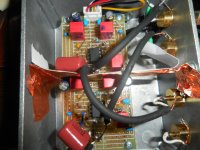
On the photograph, the right channel input cable gets close to R70, but only to the side of R70 that is connected to the negative input of the left-channel op-amp, which carries a non-amplified signal. The dampers are soldered straight to the input connectors and the right-channel input connector is adjacent to the left-channel output connector. Does cutting out R3 and C4 or putting a shield between the left output and right input connector help?
If you should have a couple of capacitive crosstalk paths that are about equally strong, eliminating one with a shield will only give a minor improvement. For example, suppose there is capacitive coupling from the wires of R70, R80, R90 to C2 and about the same amount from the left output connector and its resistor to the right input connector and its damper. You then have to shield both to get a substantial improvement.
Possible receiving parts: R13, C2, R6, R3, C4, right-channel positive op-amp input, all wiring and copper islands and the connector that are connected to either side of C2.
Possible transmitting parts: anything connected to a left-channel node with a signal on it, probably an amplified signal:
Left-channel op-amp output, R40, R70, R80, R90, C60, C50 (side that is not connected to the negative op-amp input), R110, and their connecting wires, connector and copper islands.
On the photograph, the right channel input cable gets close to R70, but only to the side of R70 that is connected to the negative input of the left-channel op-amp, which carries a non-amplified signal. The dampers are soldered straight to the input connectors and the right-channel input connector is adjacent to the left-channel output connector. Does cutting out R3 and C4 or putting a shield between the left output and right input connector help?
If you should have a couple of capacitive crosstalk paths that are about equally strong, eliminating one with a shield will only give a minor improvement. For example, suppose there is capacitive coupling from the wires of R70, R80, R90 to C2 and about the same amount from the left output connector and its resistor to the right input connector and its damper. You then have to shield both to get a substantial improvement.
Apart from your other recommendations, what about pins 1 and 5 of the 627? Trim pins..? I can cut them flush with the body. There's no "If not used..." guidance in the datasheet.
I think they should be fairly harmless. The signal voltage swing on the left channel's offset trimming pins should be much smaller than on the left channel output, while the offset trimming pins and their copper islands are further from the right channel. The right channel offset trimming pins are also far less sensitive to injected interfering currents than the open input.
Hi Chris,You beat me to building the first MvdG phono preamp, but I do have a chassis ready. Maybe I can be second! And everybody always remembers who came in second. Arf!
All good fortune,
Chris
Did you ever complete your Marcel preamp project?
Still working on the perf-board prototype. PCB version is further out, unfortunately.
All good fortune,
Chris
All good fortune,
Chris
New things done to-date:
1) Bridged all unused 5-position breadboard strips to the center backside Gnd.
2) Isolated (dismounted) the Right input RCA connector; wrapped it in a Ziplock bag and closed the lid. No plug.
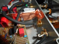
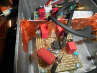
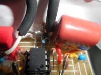
3) Separated the Left and Right channel circuitry with grounded copper tape in an attempt to form a barrier between C80A&B and R13/C2/R6.
4) Removed U2.
5) Removed the R&L input dampers R3/C4 and R30/C40.
Impressions:
The combo of #1, 3 and 5 may have provided the attached improvements. #2 gained nothing. #4 did nothing good. I did #1 and #5 at the same time.😡 #3 maybe helped.
Attached are:
1) One pic of the previous “No plug Ghost 6-25-25”
2) Three current pics: “No plug Ghost”, “1K plug Ghost” and “Close-up 1K plug Ghost”.
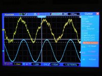
3) Two new and different pics of the square wave as input.
4) Four pics now with the Right channel driven: “No plug - Left”, “1K plug - Left”, “Close-up no plug - Left” and Close-up 1K plug – Left.
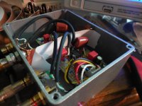
5) A number of pics of the attempt to separate U2 Left from U1 Right componentry with 1” wide conductive copper adhesive tape. The tape exactly bisects the circuitry from board level up to a 1” high shield.
Observations re attached pics 1 - 4.
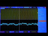
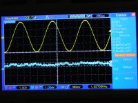
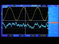
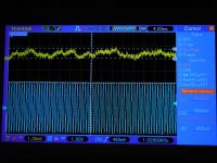
1 & 2: The current vs. last week’s “No plug Ghost” are dramatically improved, resp. A trace of 1kHz sine remains in the current Ghost.
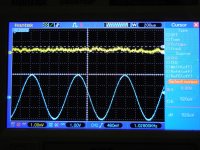
2: “1K plug Ghost” and “Close-up 1K plug Ghost” are the cleanest yet without a trace of the 1KHz Left signal.
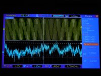
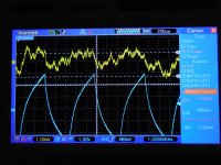
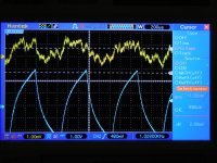
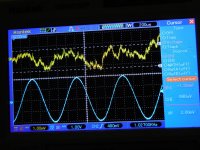
3: The square wave Ghost has lost much definition and sharpness. Less obvious.
4: All of these “golden” Right-driven, Left Ghost shots are nearly equaled by those from 2), above.
5) The U1/U2 circuits shield was the best I could come up with. ("B-F" means - From back to front, in-order. )
Question:
1) Looking at the "1K plug" Right and Left pics what level of hash noise is explainable as in self-generated noise from Rs and the op amp or the scope?
1) Bridged all unused 5-position breadboard strips to the center backside Gnd.
2) Isolated (dismounted) the Right input RCA connector; wrapped it in a Ziplock bag and closed the lid. No plug.
3) Separated the Left and Right channel circuitry with grounded copper tape in an attempt to form a barrier between C80A&B and R13/C2/R6.
4) Removed U2.
5) Removed the R&L input dampers R3/C4 and R30/C40.
Impressions:
The combo of #1, 3 and 5 may have provided the attached improvements. #2 gained nothing. #4 did nothing good. I did #1 and #5 at the same time.😡 #3 maybe helped.
Attached are:
1) One pic of the previous “No plug Ghost 6-25-25”
2) Three current pics: “No plug Ghost”, “1K plug Ghost” and “Close-up 1K plug Ghost”.
3) Two new and different pics of the square wave as input.
4) Four pics now with the Right channel driven: “No plug - Left”, “1K plug - Left”, “Close-up no plug - Left” and Close-up 1K plug – Left.
5) A number of pics of the attempt to separate U2 Left from U1 Right componentry with 1” wide conductive copper adhesive tape. The tape exactly bisects the circuitry from board level up to a 1” high shield.
Observations re attached pics 1 - 4.
1 & 2: The current vs. last week’s “No plug Ghost” are dramatically improved, resp. A trace of 1kHz sine remains in the current Ghost.
2: “1K plug Ghost” and “Close-up 1K plug Ghost” are the cleanest yet without a trace of the 1KHz Left signal.
3: The square wave Ghost has lost much definition and sharpness. Less obvious.
4: All of these “golden” Right-driven, Left Ghost shots are nearly equaled by those from 2), above.
5) The U1/U2 circuits shield was the best I could come up with. ("B-F" means - From back to front, in-order. )
Question:
1) Looking at the "1K plug" Right and Left pics what level of hash noise is explainable as in self-generated noise from Rs and the op amp or the scope?
Attachments
-
 No Plug Ghost 6-25-25.JPG470.7 KB · Views: 10
 -
 Shield End 2.JPG459.2 KB · Views: 10
 -
 Shield End 1.JPG429 KB · Views: 10
 -
 B-F; R13,C2,Shld,R6,Jmp-pin3.JPG328.9 KB · Views: 12
 -
 Shield Top.JPG470.7 KB · Views: 13
 -
 Shield overview.JPG410.2 KB · Views: 13
 -
 Close-up 1K plug - Left.JPG586 KB · Views: 12
 -
 Close-up no plug - Left.JPG543.1 KB · Views: 6
 -
 1K plug - Left.JPG470.6 KB · Views: 6
 -
 No plug - Left.JPG411.6 KB · Views: 6
 -
 No plug Square Ghost 2.JPG441.9 KB · Views: 6
 -
 No plug Square Ghost 1.JPG461.2 KB · Views: 9
 -
 Close-up 1K plug Ghost.JPG577 KB · Views: 8
 -
 1K plug Ghost.JPG493.1 KB · Views: 9
 -
 No plug Ghost.JPG473.3 KB · Views: 9
Rough estimate:
A RIAA correction curve is similar to a first-order low-pass at 50 Hz. The noise bandwidth of a first-order low-pass is π/2 times the cut-off frequency, so that's about 80 Hz. You lose about 16 Hz due to the subsonic filter, but the fact that the transfer is flat between 500 Hz and 2122 Hz at about 1/10 of the low-frequency gain compensates for that. All in all, 80 Hz with respect to the gain of about 2000 times that you have between 16 Hz and 50 Hz.
The typical input noise voltage density of the OPA627 is somewhere between 4.8 nV/√Hz and 7.5 nV/√Hz at these frequencies, say about 6 nV/√Hz. The 1 kohm resistor produces about 4 nV/√Hz. All other contributions are much smaller (for this specific case with 1 kohm source and no A- or ITU-R 468-weighting).
The root of the sum of the squares is roughly 7.2 nV/√Hz. The root of the noise bandwidth is almost 9 √Hz, so you have about 65 nV RMS times the low-frequency gain of 2000, or 130 uV RMS at the output. Assuming a Gaussian distribution, the quasi peak-peak value is about 6 times more, 780 uV quasi peak-peak.
Whoa - slow down...The root of the sum of the squares is roughly 7.2 nV/√Hz. The root of the noise bandwidth is almost 9 √Hz, so you have about 65 nV RMS times the low-frequency gain of 2000, or 130 uV RMS at the output. Assuming a Gaussian distribution, the quasi peak-peak value is about 6 times more, 780 uV quasi peak-peak.
So Marcel, by "quasi peak-peak" a level is determined by injecting a signal into a circuit like the attached "Q-P circuit"? Or is there a distinction between Q-P and Q-P-P? Google doesn't seem to recognize quasi peak-peak. All of my measurements are in Vpp. When you say a rough estimate of 780uV Qpp that means for what - broadband noise, pink or white..? Is that 780uV Qpp noise viewable on a scope? Is that what I'm seeing in the "1K plug" screen shots? Should it be divided by 2 to get the "peak" value????
Attachments
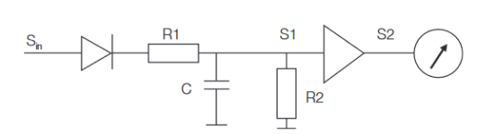
I meant an estimate of the value you should see on an oscilloscope as the difference between the positive and negative peaks. Spectrally, the noise is strongest between 16 Hz and 50 Hz because the gain of the RIAA amplifier is highest in that frequency range.
Noise usually (though not necessarily) has a Gaussian distribution, the RMS value is the standard deviation. Gaussian random signals stay between -3 and +3 standard deviations most of the time, so 6 standard deviations is a reasonable rule of thumb for the value you will read off from an oscilloscope. It's not a real peak-to-peak value though, because the tails of a Gaussian distribution extend indefinitely.
Given the RIAA amplifier bandwidth, the probability distribution and some very rough guesstimates, I expect that the noise you measure will exceed +3 or -3 standard deviations about once every 22 seconds, and +8 or -8 standard deviations about once every 1.5 million years.
- Home
- Source & Line
- Analogue Source
- OPA1656 Phono Preamp: Split from OPA1656 thread