No, I was surprised finding that 3Hz was mentioned on several topics as the cone waffle frequency, even if harmonics were also present. There were also other questions related on belt noise when the mechanical 33/45rpm lever didn't lower as it should, touching the belt's border. I'd have to check on that too, even if I will never use that lever, as I never had any 45rpm discs or will have.He did indeed but where again did you get the definitive opinion that your cone waffle was 3.0Hz? IOW, the waffle could be anything. It's linked to a resonant environment which includes the cartridge to arm, the arm to plinth, the plinth to the floor, the floor to the room and back again, round and round. You never measured the flap freq did you..? And you never said what the Thorens was mounted on (i.e it has a touchy spring isolation mech).
The opinions for the "waffle" were to float the TT with springs on the bottom, and measurements were made proving the efficiency of the isolation. It did start at 3Hz though.
My wooden floors are not floating either: it's solid wood boards placed directly over concrete floor. No sub-structure.
This time I will have to use a separate table to place the Thorens when I use it. So I am open to suggestions on that.
Probably, with a big inductor or settling for negative real poles.
No inductors of any kind, Andre.
But what about moving the servo to the first stage and add the HP filter to it?
Would that be a better option, not amplifying the low frequencies rumble as we do now?
Comes from here:I don't understand what you mean. R4 in post #253 could be increased to get more gain.
https://www.analog.com/media/en/training-seminars/design-handbooks/Op-Amp-Applications/Section6.pdf
Starting pg 6.11 Jung goes through the basics of RIAA EQ, different topologies and whatnot then on pg 6.17 introduces a new external element to the "N" feedback network called R4. R3 is still the gain R and the Rs and Cs still perform the EQ but the new R4 and the old R3 (albeit changed in value from previous example) divide the voltage seen at -IN by five. In this case (pg 6.22) it's a MC cart design where a 5x opamp is needed thus assuring a min Av of x5 and the lifting the mid-band gain from 40 to 45dB. Now I don't understand how a 5x boost in gain equates to a 5dB increase. I am missing something for sure.
But, the question is can this trick be applied to the TI quasi-Lipshitz's RIAA feedback network shown with the OPA1656 on pg 19 of the datasheet? See attached example.
Attachments
Are you saying that the participants did things with springs which brought the 3Hz waffle down to near-nothing or the acceptable result was 3Hz? It seems like the fixers are attacking an inherent sub-sonic resonance in the plinth <=> sprung deck system b/c 3Hz is pretty much out-of-the-ballpark for stylus/head-shell/tonearm induced resonance (i.e. 7-12Hz, 8-15Hz and such depending on the info source) plus it is commonly reported with this deck. Going on that theory, something about the table system is shaking the platter at 3Hz regardless of system volume - even if somehow bolted to a concrete pillar. Is that the gist? Hope not. Have you read about folks trying sorbothane? It's well known for vibration absorbance - converts to heat. Aka viscoelastic polymer.The opinions for the "waffle" were to float the TT with springs on the bottom, and measurements were made proving the efficiency of the isolation. It did start at 3Hz though.
So, a 2nd or 3rd order capacitor input S-K filter could be fashioned (w/o the input buffer) such that the raw cart output saw an equivalent R of 47K over the audio band or close to? The 20 - 20kHz input Z of a 2nd or 3rd order S-K filter looks complicated to me. Not sure you meant that re full-bandwidth.At 20 Hz, the cartridge still behaves as a resistor with a value far below 47 kohm.
So, a 2nd or 3rd order capacitor input S-K filter could be fashioned (w/o the input buffer) such that the raw cart output saw an equivalent R of 47K over the audio band or close to? The 20 - 20kHz input Z of a 2nd or 3rd order S-K filter looks complicated to me. Not sure you meant that re full-bandwidth.
I think so, but with a noise penalty.
The biggest noise source in a moving-magnet RIAA amplifier is usually the noise current with RMS value √(4kT∆f/R), or density 0.5869 pA/√Hz, of the 47 kohm termination resistor, its momentary value is called iR1 in these sketches. You add the noise current of R2 to that, worsening it to 1.03 pA/√Hz.
On top of that, there are some extra noise voltage terms related to the resistor noise current flowing through the capacitors. Those only have an impact at very low frequencies, where you don't hear noise well anyway.
Whether 1.03 pA/√Hz is enough to worry about depends on who you ask. The resulting noise level is normally well below record surface noise, but it sounds sharper, so it is not necessarily masked well.
P. S.: Apologies for the sloppy notation (mixing impedances and momentary currents) in the last schematic.
P. S. 2: Regarding the sharp sounding noise current: apply a Norton-Thevenin transformation to the noise current sources and the cartridge impedance and you see that white input noise current has the same effect as noise voltage in series with the cartridge that is proportional to the cartridge impedance and that therefore rises substantially with frequency.
P. S. 3: At frequencies where the capacitors C1 and C2 are more or less short circuits, the 22.6 kohm resistor does not contribute to the input impedance, because it has the same voltage at both terminals. The input impedance therefore tends to 47 kohm.
P. S. 4: I forgot to draw R1 in the third and fourth schematics. It should be connected between the positive op-amp input and ground, of course.
Last edited:
Subjectively sharp sounding noise when phono preamp has cartridge at its input is a typical attribute of higher input noise current of the phono preamp in combination with low input voltage noise of the preamp. I have listened to "noise" when measuring opamp based preamp total noise with cartridge and for ADA4898 with 2.4pA/rt(Hz) current noise density and 0.9nV/rt(Hz) voltage noise density this "sharp sounding" noise is typical. It is always good to compare maths calculations with real life experience. Both is important.
@JRASo, a 2nd or 3rd order capacitor input S-K filter could be fashioned (w/o the input buffer) such that the raw cart output saw an equivalent R of 47K over the audio band or close to? The 20 - 20kHz input Z of a 2nd or 3rd order S-K filter looks complicated to me. Not sure you meant that re full-bandwidth.
there is absolutely nothing wrong with all your questions, but have you ever considered to use LTSpice.
There you will have an immediate feedback on most of your questions like deviation from Riaa , noise behaviour, and the effect on the FR when using a servo, all with remarkable accuracy.
Using LTspice can really be very rewarding in helping you to answer all kinds of “what if” questions.
There are enough people on the forum willing to help you to make a start
What LTSpice can’t do is telling you how the sound perception will be for a certain topology or component choice.
That can only be established by extensive listening
Hans
It is always good to compare maths calculations with real life experience. Both is important.
OK. So far, on this thread, my calculations and my hypothesis for the original problem match pretty well with your and JRA's real-life experience.
I have simulations (or calculations), real world measurements and finally listening impressions. Because I find all of them to have equal importance. Simulations or estimations are only as good as are the models. And the models are sometimes inadequate, as in case of simulation of LT1028 with MM cartridge. The reason was already mentioned several times.
BTW, IMO the approach with higher order HP filters here is overcomplicated and may have caveats.
BTW, IMO the approach with higher order HP filters here is overcomplicated and may have caveats.
In another thread on DiyAudio I have measured some time ago the noise of a large number of the LT1028, LT1128 and AD797.
What came out was that the LT1028 and LT1128 are “commercialy” specified and do not meet the noise figures when driven with differing resistance values at plus and minus input by a rather large amount.
However, the AD797, also having bias compensation, was quite close to the specs and produced much less additional noise with differing resistance values at both inputs.
That LTspice can’t produce reliable noise figures in such cases has everything to do with bad specifications, but in most case noise projections by LTSpice are quite accurate.
Hans
BTW, IMO the approach with higher order HP filters here is overcomplicated and may have caveats.
Just a gut feeling or have you got calculations, simulations, measurements and/or experience to back that up?
I only use a second-order filter below 5 Hz or so (and I used to use a simple first-order filter below 20 Hz when the IEC amendment to the RIAA curve was still applicable) and I never saw the cones flapping, but then again, that's with a different turntable in a different house and at a different volume.
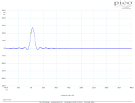
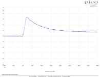
I was talking about "click response" of the higher order HP system in another thread and it was probably not well understood. Below is the explanation - 1st measurement is an impulse to simulate vinyl click or mistracking. 2nd measurement is a phono preamp output. We can see a long "tail" in output settling, due to combination of circuit HP time constants. In case of more clicks, the output may easily saturate before the transient fades out. This is why I am concerned of higher order HP circuits.


Last edited:
Square law type transfer non-linearities can be more critical in pre-RIAA networks. In the case of steady state sinusoidal testing there exists a DC spectral component that is hidden from view. A differing amplitude steady state sinusoid has different amplitude DC spectral component. For the "click response" the period of the single sided click, the DC shifts of magnitude much greater according to the RIAA response with a tail following some RC time-constant of capacitance coupling.
In my view it is best to maintain DC coupling throughout to avoid this form of RIAA magnified non-linearity. In a recent MC application this was done with potentiometer trimming on the input followed by DC servo thermal control variance at the output. This only has single pole DC adjustment below 5 Hz or so and doesn't move the low frequency driver. Transients recover immediately as far as I can tell and care about.
In my view it is best to maintain DC coupling throughout to avoid this form of RIAA magnified non-linearity. In a recent MC application this was done with potentiometer trimming on the input followed by DC servo thermal control variance at the output. This only has single pole DC adjustment below 5 Hz or so and doesn't move the low frequency driver. Transients recover immediately as far as I can tell and care about.
Last edited:
I was talking about "click response" of the higher order HP system in another thread and it was probably not well understood. Below is the explanation - 1st measurement is an impulse to simulate vinyl click or mistracking. 2nd measurement is a phono preamp output. We can see a long "tail" in output settling, due to combination of circuit HP time constants. In case of more clicks, the output may easily saturate before the transient fades out. This is why I am concerned of higher order HP circuits.
View attachment 1424242 View attachment 1424243
I already answered this as far as I could on the other thread: https://www.diyaudio.com/community/...rworth-high-pass-included.413649/post-7928085
What I can add to it now that you have clarified your question is that when a cartridge produces a series of pulses with nonzero average values in the same direction, its output signal has a DC component. I don't really see how that is possible with a cartridge consisting of an inductor and a magnet.
Like Hierfi suggested, you could get a DC component when the pulses (whatever they may look like) go through something with even-order non-linearity. In that case, I would still expect something with a subsonic filter to be less affected than a DC coupled circuit.
Regarding your impulse response, I think you mainly see the RIAA poles. The nose must come from the pole with 318 us time constant and the rest from the pole with 3.18 ms time constant.
@JRA actually uses a third-order subsonic filter, so if that causes some problem with scratchy records, JRA should have noticed it already.
To your point I agree that an inductor and a magnet can't generate DC, rather instead more akin to a capacitive coupled step function into some resistive load. Yet a cartridge can produce variant mark-space ratio signals that wouldn't entirely eliminate impulse response type artifacts being present.
Notwithstanding the non-linearities mentioned earlier, the resistors used in the feedback from the inverting terminal to ground in a typical implementation of phono network are usually low value. These require a moderately large value of capacitor to create some desired low frequency roll off. This capacitor is considered problematic in being cross-purposed in the need to create a pole and also eliminate its own artifacts, that include distortion and/or dielectric artifacts. In other words non-COG/NPO types that can be more sonically influential than anything else, for better or worse.
Notwithstanding the non-linearities mentioned earlier, the resistors used in the feedback from the inverting terminal to ground in a typical implementation of phono network are usually low value. These require a moderately large value of capacitor to create some desired low frequency roll off. This capacitor is considered problematic in being cross-purposed in the need to create a pole and also eliminate its own artifacts, that include distortion and/or dielectric artifacts. In other words non-COG/NPO types that can be more sonically influential than anything else, for better or worse.
- Home
- Source & Line
- Analogue Source
- OPA1656 Phono Preamp: Split from OPA1656 thread
