By the way, the pole-zero extraction program I use is LINDA, written by Frank Verwaal when he still worked for the late Catena Microelectronics in Delft. It runs quite well in a DOSBOX under Linux. I'll post the results in the other thread.
The +1 error leads to +/-0.05dB when distributed in both directions.It's about 0.04 dB actually, not 0.1 dB.
Ed
Double-check against a simulator. This is not a case of adding pure real and imaginary numbers.
Ed
Ed
You have to take into account the + 1 term when dimensioning the RIAA correction network, such that the extra zero around -400π krad/s is the only error it causes.
When there is an extra zero at -400π krad/s, corner frequency 200 kHz, the error it causes at 20 kHz is 20 dB • 10log(√(1 + (20 kHz/200 kHz)2)) = 10 dB • 10log(1 + (20 kHz/200 kHz)2), which is about +0.04 dB. It follows straight from Pythagoras's theorem, you don't need a damn simulator for that.
I can look up the precise zero location this evening; I think it is a bit more negative than -400π krad/s, but not much. -400π krad/s must be about right, as the corner frequency is roughly the mid-band gain times the corner frequency of the highest RIAA pole, so 100 times 2122 Hz.
Last edited:
The corner frequency is 210KHz. The phase at 20KHz is not exactly 90 degrees.
Ed
Okay, I am using the same RIAA network and adding +1.You have to take into account the + 1 term when dimensioning the RIAA correction network, such that the extra zero around -400π krad/s is the only error it causes.
Ed

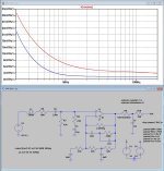
The reason why I personally prefer to avoid the extra supersonic noise from the 1+ effect is shown in the 1st attachment.
I have added a noiseless 100R resistor at the output, alternatively coupled to a grounded 1pF and 7.64nF cap for getting the 208Khz pole, and of course also with a virtual MM cart connected to it's input.
This shows the difference in noise output beyond 200Khz with extra filter in blue and without +1 filter in red.
Further have I simulated the A-Weighted noise in the audio range from 20Hz to 20Khz with a 500mH and 600R MM cart attached
At the output this adds up to 45.5uV noise, or with a gain of 39.66dB into 474nV equivalent input noise.
When using a MM with 5mV@1Khz at 5cm/sec, this results in a fabulous S/N of 80.5dBA, thanks to the very good OPA1656.
Hans
Attachments
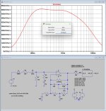
Hans,I stopped here.
First the rise in FR beyond 100Khz has to be solved.
Hans
Can ou upload the .asc file of your simulation?
Thanks!
Could very well be, but I didn’t see any parentheses at either C6 or C7.Shouldn't C6 be 2u2F for two pole HPF?
Much thanks,
Chris
Hans
Yeah, now I see, thx.Here I mean C6 from your post #306, which is C2 in Marcel's post #248
Will see what difference it makes in the simulation.
Hans
Very minor improvement in low-frequency noise and a better subsonic filter response (closer to maximally flat).

I forgot one thing: a very small noise density increase around 450 Hz because the series capacitor doesn't tune out the 500 mH cartridge reactance there anymore.
With a fabulous 80.5dBA, you may safely forget this 🤣I forgot one thing: a very small noise density increase around 450 Hz because the series capacitor doesn't tune out the 500 mH cartridge reactance there anymore.
Hans
I assume it is a noise with a MM cartridge related to 5mV/1kHz input. Is SNR 80.5dBA "fabulous", or just as good as to be expected?With a fabulous 80.5dBA,
That’s exactly what was mentioned in #327.I assume it is a noise with a MM cartridge related to 5mV/1kHz input.
80.5dBA with Cart included is a very good figure independent of whatever expectation.Is SNR 80.5dBA "fabulous", or just as good as to be expected?
Hans
It is very good, I agree. Below the result with cartridge included, real world measurement (OPA627, LT1010, servo OPA134).80.5dBA with Cart included is a very good figure independent of whatever expectation.

Very good, however not fabulous. Just what you get with the best JFET opamps. With 2SK170/2SJ74, it can be done even better.
- Home
- Source & Line
- Analogue Source
- OPA1656 Phono Preamp: Split from OPA1656 thread