I'm surprised that the MvdG topology of post #248 isn't yet recognized for what it is: a single stage RIAA plus HPF with minimal cartridge loading interactions incorporating all necessary curves while also providing the greatest possible overload margins. This combines the elegance of a single stage with highest possible performance for both noise and input level margin.
A side benefit is that, with original posted values, the largest signal path capacitors are 6u8F, which can be film, or at least metal-sputtered film type, so can be built without electrolytic capacitors (probably fine if given a DC charge, but why worry?). The single stage also simplifies the power supply requirements; a single monolythic op-amp with its single + and - supply terminals requires less attention to its supply impedance than would multiple stages.
I really haven't seen anything as game changing since Tomlinson Holman's Advent 300 receiver, almost half a century ago.
All good fortune,
Chris

And I'm surprised that nobody took the effort to simulate this circuit diagram. 🤣I'm surprised that the MvdG topology of post #248 isn't yet recognized for what it is: a single stage RIAA plus HPF with minimal cartridge loading interactions incorporating all necessary curves while also providing the greatest possible overload margins. This combines the elegance of a single stage with highest possible performance for both noise and input level margin.
Hans
Yeah, I'm not smart enough to do simulations, but am working on a perf board prototype with some parts on hand and some on order. It will be a dead bug construction with some attempt to select from 2.5% and 5% capacitors by referencing some "believed correct" 1% caps on hand with several old capacitance meters and a wing and a prayer. And 1% resistors, except 475 instead of 470, because. And OPA2134 and battery power supply.
My build partner Iain (itishifi.com) is learning PCB layout with plans to have a few boards made for us and friends. New stuff for me - seems like a lots of work just to make things look pretty, but maybe generally useful when finished.
All good fortune,
Chris
My build partner Iain (itishifi.com) is learning PCB layout with plans to have a few boards made for us and friends. New stuff for me - seems like a lots of work just to make things look pretty, but maybe generally useful when finished.
All good fortune,
Chris
Last edited:
And I'm surprised that nobody took the effort to simulate this circuit diagram. 🤣
Hans
I ran it through a pole-zero extraction program. You can call that a kind of simulation, but it is so different from the simulators I use at work that it doesn't give me the feeling I'm working overtime.
Isn't that simply the +1 error? What other mechanism could cause a zero there?
All good fortune,
Chris
All good fortune,
Chris
I feel bad that I've diverted the thread, and would suggest that we somehow continue discussion on the dedicated thread:
I'm sorry,
Chris
Hi all,
While thinking about ways to speed up the settling of a single-supply single-op-amp RIAA amplifier, see https://www.diyaudio.com/community/...upply-phono-preamp-design.413571/post-7702435 , I found a way to include a second- or third-order Butterworth high-pass filter. As it may be useful outside the context of single-supply circuits, I give it a separate thread.
When you just look at the topology and ignore the component values, this is a rather conventional RIAA amplifier (you could make it even more conventional by connecting R7 in...
- MarcelvdG
- Replies: 176
- Forum: Analogue Source
I'm sorry,
Chris
Seems a diversion from this thread as well. Perhaps ask Marcel if he cares.
I believe Hans added another pole in the LTSpice Laplace for me when I was simulating my MC phono. Don't some add another pole at 50kHz or so?
Looks as the Laplace input keeps rising when the amplifier turns into unity gain?Isn't that simply the +1 error? What other mechanism could cause a zero there?
I believe Hans added another pole in the LTSpice Laplace for me when I was simulating my MC phono. Don't some add another pole at 50kHz or so?
I believe Hans added another pole in the LTSpice Laplace for me when I was simulating my MC phono. Don't some add another pole at 50kHz or so?
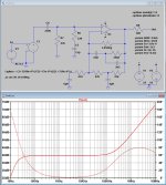
With an amp is driven from the positive input, you will have to deal with the minimum gain of 0dB.
I personally prefer to filter this in the amp, but when adding a pole in the Riaa source at 0.77usec or 207Khz, this will make the FR straight again.
At the same time I've also shown the group delay.
According to Tomlinson Holman group delay at 20Hz should be below 20msec, that's why I simulated a 2nd order and not a 3rd order rumble filter.
Hans
Attachments

As carlmart and JRA were both interested in subsonic filtering, I gave them my design as an example, that's how it ended up in two threads.
Regarding the zero caused by the +1 term, I usually deal with it by calculating the error at 20 kHz and concluding it is smaller than the error you are going to get from component tolerances and rounding values to E96 values. In fact, it's still well below 1 dB over the feline hearing range, so the chances of getting complaints about it from my cat are also small.
Regarding the zero caused by the +1 term, I usually deal with it by calculating the error at 20 kHz and concluding it is smaller than the error you are going to get from component tolerances and rounding values to E96 values. In fact, it's still well below 1 dB over the feline hearing range, so the chances of getting complaints about it from my cat are also small.
Last edited:
Could not find a Grado cart called Signature 8MZ but seems that's an older body with a current 8MZ replacement stylus but no specs for compliance. FWIW there are sims I think for one or two very good and popular MM carts made by Audio Technica. The AT 540ML is one and the AT 150MLx might be another.Just to let this Grado question clear. The model it's not unknown: it's the Signature 8MZ. What is unknown is the LTspice model for it.
And I am still loitering and absorbing 10th of 1% of the sub-sonic wisdom here. Have also been absent for a short while. Other than Life, I've been distracted with tuning a new-to-me cart fitted to a new/old-to-me linear tracking TT from the 80s (AT 150MLx cart and Mitsubishi LT-30 full-auto TT- which has a better mute switch than little brother LT-20, btw), resp. The AT MicroLines are super sensitive to everything b/c they are so sharp. Azimuth, Zenith, VTA and SRA setup is tedious. I have to walk away sometimes.As carlmart and JRA were both interested in subsonic filtering, I gave them my design as an example, that's how it ended up in two threads.
But anyway I do intend to take scope shots of a pop/tick with a conventional/buffered 3rd order 18Hz S-K HP filter in-front of the OPA626 RIAA EQ. Here's a repeat of where I am now. The S-K filter is the insert on Pg 2. Then it jumps back to Pg 1, Sorry.
Attachments
Did you try a different op amp vs. the rambunctious opa1656? Like the opa1641/42 or the opa627? I haven't a clue of what that graph shows.I stopped here.
First the rise in FR beyond 100Khz has to be solved.
The graph shows frequency response rising at very high frequencies (a "zero") caused by "the +1 error" which is itself caused by a non-inverting feedback amplifier's inability to have less than unity gain, and a test signal assumed to be flat forever.
Opinions vary on whether or not this matters. Real records are cut with considerable ultrasonic filtering, to accommodate real cutter heads' limitations, so the issue is somewhat artificial. Stylus / groove wall interactions get murky at short wavelengths, complicating it further. Some folk will tack an RC LPF on the output if they're concerned.
All good fortune,
Chris
I don't see the 2122Hz pole at 2122Hz. That's what is befuddling. I thought this was to be a FR sim of Marvel's RIAA EQ circuit.The graph shows frequency response rising at very high frequencies (a "zero") caused by "the +1 error" which is itself caused by a non-inverting feedback amplifier's inability to have less than unity gain, and a test signal assumed to be flat forever.
And who cares about the RIAAs max hi-freq limit of ~50-100KHz. @20dB gain @ 21kHz and @ -6dB slope beyond, many op amps hit the open-loop 0dB wall at about that. Or have I had too many cocktails tonight.
The post filter I see has a wee problem. The R has to be large enough to limit op amp's Vo loading at high freqs but not too big to screw with the output resistance wrt unknown downstream loads. EG: Big C, + small R = R//feedback elements @ HF = maybe Vo overload. Big R + small C = need for output buffer.
Bedtime...
The error due to the "+1" is not much smaller than the error due to 2% capacitors (+0.1dB at 20KHz versus +/-0.2dB). This matters if one is aiming for world-class EQ accuracy.
Ed
It's about 0.04 dB actually, not 0.1 dB.
I don't see the 2122Hz pole at 2122Hz. That's what is befuddling. I thought this was to be a FR sim of Marvel's RIAA EQ circuit.
And who cares about the RIAAs max hi-freq limit of ~50-100KHz. @20dB gain @ 21kHz and @ -6dB slope beyond, many op amps hit the open-loop 0dB wall at about that. Or have I had too many cocktails tonight.
The graph of post #306 shows the deviation from an ideal RIAA response, basically what I had already checked with my pole-zero extraction program. Ideally it should just be a Butterworth high-pass filter, but there are some small differences in the deep subsonic region and some at ultrasonic frequencies due to the + 1 term.
- Home
- Source & Line
- Analogue Source
- OPA1656 Phono Preamp: Split from OPA1656 thread