So, do we have a final schematic of Marvel's phono preamp?
1) Do we simply put say ~ 15nF at the output for the +1 problem?
2) Can we see a Bode plot of 40Hz and down? Is 30Hz preserved? 20Hz?
3) Can the 1KHz gain be increased by say +5dB as was part of my original wish list for a low gain system?
Hats off to all those here smarter than I!
The schematic below would be my increased gain version, gain roughly 46 dB at 1 kHz. With midband gains of 40 dB or more, adding extra filters to correct for the + 1 is quite unnecessary in my opinion, as long as the + 1 is taken into account when determining the component values, as it always was. If you really want to, you can put a first-order low-pass with 382.3 ns time constant between the op-amp and R4. Like Hans wrote, it is a good idea to still have a resistor straight at the output to prevent sharp transmission line resonances that might cause instability in the next stage.
As implicitly suggested by hbtaudio, I've split up the former R6 into two parts, R0 before and R6 after C2. The main advantage is that it gives me more control over the input time constant, it also provides a discharge path to C2 when there is no cartridge connected.
Besides the ultrasonic effect, the + 1 term also changes the slope of the subsonic filter below about 1.1 Hz. For the second-order version, this is corrected for by C2, for the third-order version, it is not corrected. If you should find it necessary to correct for it, put a first-order high-pass with 141.9 ms time constant at the output. I think it's quite unnecessary, as the third-order response is already close to -70 dB at such low frequencies.
According to LINDA, the poles and zeros are:
Second-order version:
Poles:
-13.340 krad/s
-316.937 rad/s
-7.102 rad/s
(-70.738 +/- 71.402j) rad/s
Zeros:
-2.616 Mrad/s
-3.146 krad/s
-7.048 rad/s
-736.190 mrad/s
-149.537 frad/s (equivalent to a cycle per 1.33 million years. This zero should really be at 0, but due to numerical inaccuracies, LINDA finds an absurdly small nonzero value.)
This leads to the following deviation from an ideal RIAA response over the 100 rad/s (15.9155 Hz) to 100 krad/s (15.9155 kHz) frequency range:
Upper graph: magnitude in dB, lower graph: group delay in seconds. Please subtract 339.38 dB from the numbers in the upper graph to get it normalized to the gain at 1 kHz. At 100 rad/s, there is a -3.07 dB deviation from the ideal RIAA response, as was to be expected with a 16 Hz Butterworth subsonic filter.
Third-order version:
Poles:
(-49.750 +/- 86.408j) rad/s
-13.274 krad/s
-316.937 rad/s
-99.357 rad/s
Zeros:
-2.616 Mrad/s
-3.164 krad/s
-7.046 rad/s
-717.159 mrad/s
0 rad/s
Resulting deviation from an ideal RIAA response from 100 rad/s (15.9155 Hz) to 100 krad/s (15.9155 kHz), now add 41.14 dB to the values in the upper graph to get it normalized to 1 kHz:
With respect to 1 kHz, the response has dropped to -2.93 dB at 100 rad/s (15.9155 Hz) due to the subsonic filtering. The deviation from the ideal RIAA response at higher frequencies is not quite as flat as in the second-order case, because the RIAA zero and second pole are slightly less accurate.
Same plot, but with the cursors placed elsewhere:
This shows that the peak-to-peak error due to the slightly less accurate RIAA zero and second pole is about 0.07476 dB.

Please explain the "as long as the + 1 is taken into account when determining the component values, as it always was." part. +1 poles at 100KHz and 200KHz were brought up and now only an added 400KHz pole because why..? What about the original zero deviation at 100Khz and up?With midband gains of 40 dB or more, adding extra filters to correct for the + 1 is quite unnecessary in my opinion, as long as the + 1 is taken into account when determining the component values, as it always was. If you really want to, you can put a first-order low-pass with 382.3 ns time constant between the op-amp and R4.
I had a little disagreement with @EdGr a couple of pages back about whether the error due to the + 1 would be 0.1 dB or 0.04 dB for the frequency range up to 20 kHz when the gain at 1 kHz is 40 dB. In the end, we figured out that it depends on how you determine the component values.
When you calculate them while neglecting the + 1 term and then in the end at + 1, you get an error of about 0.1 dB at midband frequencies that cannot be corrected with an extra low-pass filter. (That's for 40 dB gain at 1 kHz, it should be about 0.05 dB for 46 dB gain.)
When you take the + 1 into account from the start, all you get is an extra zero that causes a +0.04 dB error at 20 kHz (for 40 dB midband gain, +0.01 dB for 46 dB midband gain) and that you can correct with an extra first-order low-pass filter. (I don't see the point because of the small magnitude of the error, but still.)
The corner frequency of the zero caused by the + 1 term is to a good approximation the frequency where the magnitude of the gain should drop to unity if there had been no + 1 term. The phase shift without the zero is approximately -90 degrees there, so the magnitude of the gain becomes √2 with the + 1 term added. When you draw the Bode asymptotes, you see that it is approximately 2122 Hz times the midband gain. The higher the gain, the higher the frequency and the smaller the error up to 20 kHz.
The +1 term in the non-inverting feedback equation is only one source of error. The other source is the finite open-loop gain. The discrete-transistor pre-amps I was designing in the 1980s did not have enough open-loop gain for accurate active EQ. I went to passive EQ to eliminate both errors.
Ed
Ed
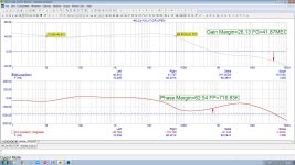
But if you make almost constant 40 dB loop gain 1Hz...60 kHz [ see attached loop gain ] the discrete-transistor preamp with transadmittance RIAA output [ https://photos.app.goo.gl/8pHWArfTaYrDsXQx9 ] is fineThe other source is the finite open-loop gain. The discrete-transistor pre-amps I was designing in the 1980s did not have enough open-loop gain for accurate active EQ
Attachments
@Nick Sukhov - The open-loop gain is ~100dB, which is as much as an IC op-amp.
I prefer open-loop gains of ~60dB. Explaining why moderate open-loop gain is preferable will derail the thread.
Ed
I prefer open-loop gains of ~60dB. Explaining why moderate open-loop gain is preferable will derail the thread.
Ed
Dear Ed,I prefer open-loop gains of ~60dB. Explaining why moderate open-loop gain is preferable will derail the thread.
Ed
but it is precisely these details that need to be understood.
So that your fears are not realized, please open a separate thread to explain this - I am very interested in your explanation.
🙂
greetings,
HBt.
1656 datasheet fig.6.5 : open loop = 70 dB @ 20 kHz. With 20 dB RIAA FR @20k you need at least 80 dB open loop, 10 dB deficitI prefer open-loop gains of ~60dB
I may do that. The topic may erupt into a flame war since everyone who uses op-amps does not want to hear about the downsides of 100-150dB open-loop gain.Dear Ed,
but it is precisely these details that need to be understood.
So that your fears are not realized, please open a separate thread to explain this - I am very interested in your explanation.
🙂
Ed
I belong to a different species.I may do that. The topic may erupt into a flame war since everyone who uses op-amps does not want to hear about the downsides of 100-150dB open-loop gain.
Ed
Protective help is to be expected from my side.
HBt.
🧙♂️
A perfectly high output impedance transconductance input stage, followed by lossy RIAA, followed by perfectly high input impedance second stage, has frequency response independent of stage gains. This isn't something easily done with the usual monolythic opamps, but is very interesting for discrete designs. I only hope that the discussion doesn't just repeat the John Curl / Bob Cordell discussions of the 1980s?, where flat open loop frequency response was promoted as a virtue in its own right, something still alive in some DIY circles.
Don't wish to sound negative, only wary. The "F-word" wars are still raging. Maybe largely in my country, where reality is teetering.
All good fortune,
Chris
Don't wish to sound negative, only wary. The "F-word" wars are still raging. Maybe largely in my country, where reality is teetering.
All good fortune,
Chris
The +1 term in the non-inverting feedback equation is only one source of error. The other source is the finite open-loop gain. The discrete-transistor pre-amps I was designing in the 1980s did not have enough open-loop gain for accurate active EQ. I went to passive EQ to eliminate both errors.
Ed
Good point. I've assumed nullor behaviour in post #381 (and everywhere), but I will have a look at what happens with a finite gain-bandwidth product.
I started a new thread which you will find to be either interesting or boring. https://www.diyaudio.com/community/threads/audio-op-amps.424425
Ed
Ed
Regarding the effect of the finite gain-bandwidth product, due to the OPA1656's fairly large gain-bandwidth product (53 MHz), the effect is rather small. The RIAA correction poles shift a bit, particularly the second one, the zero remains where it is (both in LINDA and in calculations). The first pole shifts by about -0.21 to -0.25 %, the second by -0.6 % to -0.67 %.
When R8 + R9 in the circuit of https://www.diyaudio.com/community/...split-from-opa1656-thread.377331/post-7939733 is reduced by 100 ohm, the second RIAA pole and the zero are both shifted up by about 0.285 %. The zero is then about as much too high as the pole is too low.
100 ohm lower values for R8 + R9 can be obtained by series-connecting two E96 values, as shown here:

Except for R8 and R9, nothing changed. Mind you, a slower op-amp such as an OPA627 would need a somewhat larger correction (presumably around -400 ohm rather than -100 ohm, but I haven't checked that).
When R8 + R9 in the circuit of https://www.diyaudio.com/community/...split-from-opa1656-thread.377331/post-7939733 is reduced by 100 ohm, the second RIAA pole and the zero are both shifted up by about 0.285 %. The zero is then about as much too high as the pole is too low.
100 ohm lower values for R8 + R9 can be obtained by series-connecting two E96 values, as shown here:
Except for R8 and R9, nothing changed. Mind you, a slower op-amp such as an OPA627 would need a somewhat larger correction (presumably around -400 ohm rather than -100 ohm, but I haven't checked that).
Huh..? Confused again.When you take the + 1 into account from the start, all you get is an extra zero that causes a +0.04 dB error at 20 kHz (for 40 dB midband gain, +0.01 dB for 46 dB midband gain) and that you can correct with an extra first-order low-pass filter. (I don't see the point because of the small magnitude of the error, but still.)
1) Who else, commercially speaking, knows about or worries about or even deals with and then crows about correcting a tiny mid-band gain error in the realm of 10s of 100ths of a dB? Don't component tolerances do a fine job of creating far more error?
2) And how does an external, out-of-the-loop 6dB LP filter correct any misbehavior in the "mid-band"? How does the opamp know it's even there...?
3) Isn't it time to say "good enough"? I'd. like to build this design but it seems it's still in-flux.
4) And one more thing speaking of building; the 6.8uF can/should be what kind(s)? Is 2x 6.8 = exactly 13.6uF important? I imagine that C7 is.
Last edited:
1) Probably no one, but audio hobbyists tend to be perfectionistic.
2) It doesn't. It corrects for the error at 20 kHz, but the magnitude of that error depends on the midband gain because the corner frequency of the unwanted ultrasonic zero is roughly 2122 Hz times the gain at 1 kHz. Like I wrote, I think a first-order post filter is quite unnecessary for amplifiers with a high midband gain, which is why I didn't draw any.
3) I'd say so. Yesterday Ed made a remark about loop gain that triggered me to check something I had forgotten, which led to the update of post #396. As far as I'm concerned, that's the definite version.
4) Any kind of fairly accurate film capacitor, definitely no class 2 ceramic capacitor. If I were building it, I would probably choose
https://www.reichelt.de/de/de/shop/produkt/mks2_pet-kondensator_6_8_f_5_50_vdc_rm_5-31931
because they take only little board area and you probably can't get much with less than 5 % tolerance anyway unless you are willing to pay a fortune.
C8A and C8B determine the first RIAA pole and C7 only the subsonic response, so C8A + C8B is more critical than C7. Still, the worst that could happen with 5 % tolerance capacitors and 1 % tolerance resistors is that you get about 0.5 dB too much or too little deep bass.
As usual, C5 and C6 can be 1 %, 2 % or 2.5 % tolerance film or NP0/C0G ceramic capacitors. They determine the RIAA correction zero and second pole.
Last edited:
Seems like an odd choice. Polyester dielectric can be rather nonlinear. However, maybe the phono signal is so small the cap can be considered reasonably piecewise linear for small enough signals?If I were building it, I would probably choose...
- Home
- Source & Line
- Analogue Source
- OPA1656 Phono Preamp: Split from OPA1656 thread