I have an old stock of Soviet precision metal film resistors S2-29V that I use as a reference. Compared them to Dale's 5 ppm resistors and there was no difference in the measurement area. Statistics and various practices indicate that they are most likely linear, as far as I can currently measure.
But in general, each sample of any resistor and capacitor should be tested individually before it is used in critical locations.
But in general, each sample of any resistor and capacitor should be tested individually before it is used in critical locations.

IMHO those, as Demian wrote: Vishay doesn't even publish linearity info on the Bulk Metal resistors. https://foilresistors.com/docs/63140/var.pdf
In the old days there was the Alpha Core as also none inductive as in a black plastic block.
As mentioned:
At that, negligible capacitance/inductance of foil resistors (when compared to wirewound resistors) significantly reduces
probability of self-excitation or "ringing" of amplification circuit.This is why Bulk Metal® foil resistors are such a good
choice for low-noise applications...
In the old days there was the Alpha Core as also none inductive as in a black plastic block.
MELF resistor from Token Electronics as none inductive as RFM series
In the old days there was the Alpha Core as also none inductive as in a black plastic block.
As mentioned:
At that, negligible capacitance/inductance of foil resistors (when compared to wirewound resistors) significantly reduces
probability of self-excitation or "ringing" of amplification circuit.This is why Bulk Metal® foil resistors are such a good
choice for low-noise applications...
In the old days there was the Alpha Core as also none inductive as in a black plastic block.
MELF resistor from Token Electronics as none inductive as RFM series
Attachments
Yes, in many cases.The better resistor is two resistors in series instead of one. 🙂
Also, by connecting four identical resistors in a series-parallel circuit instead of one and comparing the results, we can understand whether the resistor is linear or not.
One resistor ARG05FTC1502:
https://content33-foto.inbox.lv/albums/e/elterra/ResitorLinearityMeasurements/1R.jpg
Four ARG05FTC1502:
https://content33-foto.inbox.lv/albums/e/elterra/ResitorLinearityMeasurements/4R.jpg
hi excuse me Which model precisely ? thank you very muchmy $130 Juli@ does that good with much narrower noise skirt
here's one RMAA test: RightMark Audio Analyzer test : Juli@ loop
I am about to build the 1kHz oscillator designed by Victor.
I intent to design with leaded parts (no smd).
My question:
I have difficuties finding the BAS70, I would like to know a replacement (leaded) for BAS70 please.
I intent to design with leaded parts (no smd).
My question:
I have difficuties finding the BAS70, I would like to know a replacement (leaded) for BAS70 please.
As a replacement for BAS70 you can use two single through hole diodes:
https://eu.mouser.com/ProductDetail/Vishay-Semiconductors/BAT83S-TR?qs=WLTup5mM6hhDIDIvrvxhEg==
or
https://eu.mouser.com/ProductDetail/Vishay-Semiconductors/SD101A-TR?qs=IenFidxwq1RH4/rg/e4u3A==
https://eu.mouser.com/ProductDetail/Vishay-Semiconductors/BAT83S-TR?qs=WLTup5mM6hhDIDIvrvxhEg==
or
https://eu.mouser.com/ProductDetail/Vishay-Semiconductors/SD101A-TR?qs=IenFidxwq1RH4/rg/e4u3A==
-V supply is the reference voltage for AGC. You will get 1.25 times lower output voltage. You can change the R7 value for to get output voltage back.
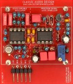
This is my version of Victors 1kHz oscillator.
I must explain, my design is with leaded parts, because I cannot design with surface parts because of my eyes.
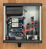
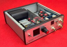
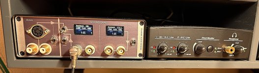
I plan to use the 1kHz oscillator in an existing design (see photo’s)
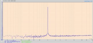
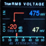
This is a 1 kHz ref. signal source with a 60dB attenuator (1dB step) and a dual output driver (very low output impedance). All is controlled by Arduino.
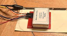
The 1kHz oscillator works great.
I have some difficulties getting the oscillator to start, but I received fast and good help from Vicnic.
The specification of my 1kHz version is not at level of the original Vicnic design, but I will later optimize according to Victors recommendations.
For you information ......... a couple of photo's of the system, my layout of the oscillator and the very first test results.
I must explain, my design is with leaded parts, because I cannot design with surface parts because of my eyes.
I plan to use the 1kHz oscillator in an existing design (see photo’s)
This is a 1 kHz ref. signal source with a 60dB attenuator (1dB step) and a dual output driver (very low output impedance). All is controlled by Arduino.
The 1kHz oscillator works great.
I have some difficulties getting the oscillator to start, but I received fast and good help from Vicnic.
The specification of my 1kHz version is not at level of the original Vicnic design, but I will later optimize according to Victors recommendations.
For you information ......... a couple of photo's of the system, my layout of the oscillator and the very first test results.
Attachments

VERY nice design!
What audio interface (sound card) did you use with Audio Tester?
Also, a nice Arduino project.
Cheers,
Bob
What audio interface (sound card) did you use with Audio Tester?
Also, a nice Arduino project.
Cheers,
Bob
Hi Pizzigri,
I will absolutly not make a commercial project for any of my projects.
If anyone is interested I will be happy to share.
I have been using the setup of:
My own Soundcard interface - USB 0204 - Audio Tester - TrueRTA for more than 10 years (perhaps 20 years now)
Testing classic audio products like amplifiers - gramophones - FM receivers ect. in my small company Classic Audio.
I have now sold Classic Audio.
I have really a number of project for audio testing allready made with good documentation.
But I am not going to make any commercial project for any of the designs.
That is one very well designed, versatile tool. I really like the what you decided to display. I would definitely be interested in building one.
- Home
- Design & Build
- Equipment & Tools
- Low-distortion Audio-range Oscillator