I have a SG-505 + AA-501 combo, and today I checked their performance. The residual on the analyzer is 1.2 uV, with 400 Hz+30 kHz filter. The AA-501 in itself is 1.0 uV with shorted input. If I connect the monitor output to the oscilloscope, the noise signal is visible. I see there is some 50/100 Hz component, and I found it comes from the generator. So I replaced the two capacitors C1201 and C1210 (100 uF/20 V) to 680 uF/25 V.
The situation is a bit better. But still there is some 100 Hz. Even if I push the grounded button (not floating output).
What do you think, the big capacitors 470 uF/50 V could be replaced to, say 2200 uF, will it help? This is a 40+ year old instrument, the capacitors could be aged. Anyway the 100 uF elkos that I replaced seem good (ESR is low, I measured).
So if you have any recommendation for any other improvement I would be grateful.
I also don't understand why they used LF351 as output buffer. Its data sheet performance is not exceptional, how did they achieve 0.0001% THD? What if I replace it to something more modern opamp, like OPA1641, 1655, ...? Unfortunately it is soldered, unlike the oscillator 3x NE5534.
100Hz could easily be due to a ground connection somewhere, either having poor contact - or the reverse, where an insulating washer or similar has been left out, creating a ground loop.
Do you know what the LF351 is doing? Have you got a schematic? If it's wired as a voltage follower, its noise contribution could be lower than the preceding circuitry, whereby any gains from a modern IC will be negligible.
470uF to 2,200uF is a large jump. You will want to make sure that the rectifiers can handle the inrush current. I doubt it will be worth it TBH. The maker would've fitted larger if they could see a benefit.

The 100 Hz infiltration is not dramatic. Something like 1.5 uV vs. 1.0 uV level difference. Yes I have the Instruction Manual with the schematics, parts list, calibration instruction (nothing to be calibrated apart from the output level!). Sorry I overlooked the LF351, it goes to the rear interface. The main output is an 5534 in a tricky circuit that I not fully understand. I don't touch it 😉.
The Tek TM500 SG-505 + AA-501 is a truly outstanding THD analyzer for its time. It was designed by the founders of AP and its analog circuitry and approach is a precursor to the AP 1. Of course, the AP1's use of the PC as the human interface and for computing was revolutionary. There are, of course, IC's in the SG-505 and AA-501 that can be improved upon, but it can be difficult to predict how much improvement would be gained.. In looking at hum issues and electrolytic capacitors, don't overlook the power supply capacitors in the TM-500 mainframe you are using.I have a SG-505 + AA-501 combo, and today I checked their performance. The residual on the analyzer is 1.2 uV, with 400 Hz+30 kHz filter. The AA-501 in itself is 1.0 uV with shorted input. If I connect the monitor output to the oscilloscope, the noise signal is visible. I see there is some 50/100 Hz component, and I found it comes from the generator. So I replaced the two capacitors C1201 and C1210 (100 uF/20 V) to 680 uF/25 V.
The situation is a bit better. But still there is some 100 Hz. Even if I push the grounded button (not floating output).
What do you think, the big capacitors 470 uF/50 V could be replaced to, say 2200 uF, will it help? This is a 40+ year old instrument, the capacitors could be aged. Anyway the 100 uF elkos that I replaced seem good (ESR is low, I measured).
So if you have any recommendation for any other improvement I would be grateful.
I also don't understand why they used LF351 as output buffer. Its data sheet performance is not exceptional, how did they achieve 0.0001% THD? What if I replace it to something more modern opamp, like OPA1641, 1655, ...? Unfortunately it is soldered, unlike the oscillator 3x NE5534.
Cheers,
Bob
Thanks, I will check the raw DC +/-33 V and +11.5 V. I only need an extension board, work in progress ...
Yes, 100 Hz noise hints at a supply issue, not ground loop.
To be sure can you show a scope screen capture ?
To be sure can you show a scope screen capture ?
I built this one. Absolut excellent results….
http://diy.ucborgmann.de/index.php/en/audio-messtechnik-2/low-distortion-generator-1
P.s. Uwe was the lead engineer of the former AudioNet project…
http://diy.ucborgmann.de/index.php/en/audio-messtechnik-2/low-distortion-generator-1
P.s. Uwe was the lead engineer of the former AudioNet project…
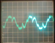
This is the AA 501 function output, when the generator output is OFF.Yes, 100 Hz noise hints at a supply issue, not ground loop.
To be sure can you show a scope screen capture ?
400 Hz filter off, SG 505 output GNDED.
Oscilloscope horizontal 5 ms/div. It looks like 50 Hz.
Strange is that if I connect the analyzer's GND post to the generator's GND post there is no change in the waveform (as it should be). However, if I connect the analyzer's GND post to the outer metal part of the BNC cable connecting them together, the hum drops. Note the generator's output common is grounded (GNDED pushbutton is in).
Attachments
There might be a PE loop issue between your O'scope and TM500; or a big, leaky transformer or ballast in the vicinity
Thanks for posting that link; I was not aware of it. The oscillator mentioned there is a very nice, modern implementation of the state variable oscillator I designed for my 3-part THD analyzer construction project published in Audio magazine. That article is available on my website at cordellaudio dot com. The idea to use a state variable oscillator was inspired by a paper by Bruce Hofer, a founder of AP, at a convention of the Audio Engineering Sociey while he was still at Tektronics. The paper was essentially a description of the SG-505 oscillator. The analyzer portion of my THD analyzer was a state variable notch filter that had JFET control of frequency and amplitude for implementation of the auto-tune function. NE5534 op amps were used in the signal path.I built this one. Absolut excellent results….
http://diy.ucborgmann.de/index.php/en/audio-messtechnik-2/low-distortion-generator-1
P.s. Uwe was the lead engineer of the former AudioNet project…
Cheers,
Bob
The hum could be reduced a bit by adding a copper flux band around the onboard transformer. Proper grounding is also important, the optimum could be found by monitoring the function output. 1.2 uV is not too bad, I think.There might be a PE loop issue between your O'scope and TM500; or a big, leaky transformer or ballast in the vicinity
Speaking of distortion measurement, Version 3 of my Tutorial for the QuantAsylum QA403 audio analyzer is now up on my website and is discussed in the QuantAsylum User Forum. The tutorial walks the reader through all of the pertinent tests for an audio power amplifier, in this case my BC-1 design, which is also described in detail on my website.
The QA403 is an outstanding piece of equipment, especially at only $600. It has pretty much all of the functionality and performance most people could need. It is just as valuable for use with small-signal circuits as well as power amplifiers. One nice feature is that it includes selectable inverse RIAA respnse shaping for measuring phono preamps. It also includes selectable A-weighting for noise measurements. Further, it includes optional user-entered weighting responses. It can usually see distortion products below -120 dB or better, and report THD down to -120 dB or better. It can sample at up to 192 kHz, allowing one to see FFT products up to at least 80 kHz. Sampling to 384 kHz may be available soon. It is powered from its USB connection to the PC on which its software resides, and it is galvanically isolated from the PC side. It has balanced I/O.
Cheers,
Bob
Hello,
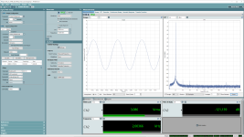
in Germany the QA403 costs 800 euros and can be bought from elektor.de. I don't know why it's 30 percent more expensive here than in America. What the QA 403 lacks for precision measurements on high-end preamplifiers or similar is an analog sine generator and a notch filter in the analyzer section. Then you can also measure precisely below -140dB THD, which is necessary when designing analog circuits with OPA1612 or OPA1656. Otherwise you only measure the combined inherent THD of the DAC oscillator and analyzer. Since I also had this problem, I developed my own analog oscillators that have a THD of below -140dB. I then had this measured in a laboratory with an APX555 from Audio Precision. Here is a picture of my oscillator at 3V RMS and 2kHz. The other picture shows the loop-back of the APX 555.
Best regards
Helmut Sell
Attachments

Hi Helmut,
Thanks for pointing these matters out. I mostly agree, as I have made similar kinds of measurements at very low levels of distortion. When doing so, I have used a twin-T notch in front of the analyzer and looked at the residual output of the analyzer on a spectrum analyzer. These are very specialized measurements, and although useful for extreme performance engineers like you and I, the distortion floor performance of the QA403, well below -120 dB when used optimally, probably fills the needs of 90% of the people using an AP. I used this approach to measure Victor's 1-kHz oscillator.
You are correct that the QA403 signal generator can be beaten by a very well-designed analog oscillator, especially a fixed-frequency 1 kHz one like Victor's. I have not yet made extreme laboratory measurements of the QA403 generator by itself, but I have heard that the QA403 generator dominates the loop back distortion floor of the QA403. BTW, everyone needs to know that the generator in the QA403 can produce continuous sinewaves in the idle mode.
I am not aware of many (any?) analog audio oscillators that are continuously tunable over the audio range (or, for example, from 10 Hz to beyond 100 kHz) that can achieve extremely low distortion in the range below -130 dB. I have been working on such a design that is continuously tunable from 10 Hz to more than 100 kHz with a logarithmic rotation dial for some time now. It uses a 5-stage state variable oscillator where the extra 2 stages are gain controls for tuning in front of the integrators that employ the Baxandall volume control technique to achieve the desired logarithmic tuning behavior over a decade with a quality 2-gang 10k linear potentiometer. It also uses a 4-phase rectifier for level detection to achieve very low AGC ripple; it uses the quadrature outputs available from the state variable oscillator to implement the 4-phase rectifier.
A very low distortion fixed-frequency twin-T notch filter in front of the QA403 would reduce the relative THD floor achievable with the QA403. If a passive twin-T is used to get the lowest possible distortion from the notch filter, the significant passive losses at the second harmonic must be compensated for. The QA403 allows for a user-defined frequency weighting to be implemented in it, so there one could compensate for the undesired twin-T losses at harmonic frequencies.
Is the oscillator you designed fixed-frequency or continuously tunable over the full audio range?
Cheers,
Bob
My EMU0404 can suppress harmonics to below -130dB in a loopback using REW's harmonic adjustment for its sinewave generator. On face value that may not be very practical for a frequency sweep tool, as the nulling of harmonics is a manual adjustment and relevant to the generated fundamental frequency and amplitude.
It also implicitly doesn't measure the generator's output signal (ie. related to just the soundcard DAC) but rather measures the DAC plus ADC/front end's harmonic outcome, although from testing using attenuators and notch filters, I sort of deduced that the harmonic contribution from the ADC/front end was identifiably less than the ADC.
Perhaps an alternative measurement system path could be to automate the harmonic nulling process as a pre-cursor to making a frequency step measurement. That would leverage the power of software to optimise whatever hardware was being used.
Hi Bob,
First of all, thank you very much for your very detailed answer. I agree with you that the QA403 is a very good and useful tool for testing power amps, etc. I bought a QA401 myself a few years ago. There was also a QA480 (analog 1kHz sine generator with twin-T notch filter). Unfortunately, I think only 25 units were built and the device is no longer available. I would pay significantly more than 250 EUR for it (price in Germany). But whatever, QA certainly had reasons for no longer producing the device.
That was also the reason why I developed the oscillators myself. I am an electrical engineer, but audio is just a hobby of mine. I will certainly never reach your skills in analog circuit technology. The project with the continuously tunable 5-stage SVO sounds very exciting...
I started building oscillators with 1kHz about 10 years ago. These were Wien bridges and then bridged-T oscillators, like the HP339A but only for 1kHz. I modified the amplitude control of the HP339A (different time constants for the integrator, etc.) and achieved a THD of around -140dB at 1kHz and 1-3V RMS output. Then I also used the state variable principle. The oscillator that I had measured with the APX555 has 4 fixed frequencies 1,2,3,5 kHz. So it is not continuously tunable. But I also built one that can be switched from 1-10kHz in 1kHz steps, with a similar performance of THD and THD+N.
In order to test my oscillators myself, I built a notch filter (state variable filter) where I can adjust the frequencies from 1kHz-20kHz in 0.5kHz steps using DIL switches. The notch filter has a Q of 1 and therefore suppresses the harmonics much less than a twin-T notch filter. An amplifier (OPA 1612) then amplifies the notch output by approx. 30dB. The attenuation at the resonance frequencies is approx. -80dB. With this filter and my R&S UPL, which then does the FFT, I can measure up to approx. -150dB THD.
Kind regards
Helmut Sell
- Home
- Design & Build
- Equipment & Tools
- Low-distortion Audio-range Oscillator