Hello Monstercore,
I don't know exactly what you mean by the sentence "My oscillator is just a DAC (150 Euro)". I understand your sentence to mean that everyone who spends 800 Euro on a QA403 or even more money on audio test equipment is basically "stupid". OK, I'll accept that. But it would be nice if you wrote, for example, how many volts RMS 0dBFS is, so that I can then work out what voltage -5.84dBFS ultimately is. I also don't understand why you do 50! averages with a 128K FFT?
Helmut Sell

My dac is a 9039q2m from cosmos. Designed for oscillator/tone generator duty.
0dbfs is 4.2Vrms.
I only mentioned the price, because for €150 you get a great tool. Not only for 1khz thd measurement but for much more measurements like frequentie respons, fase respons, IMD, step respons and a lot more. All controlled by free software.
I said nothing about the adc or measure device.
And with harmonic correction file.
Last edited:
Some notes on direct DAC and ADC measurements:
1) Usually DACs and ADCs have a "sweet spot" where the smallest harmonics appear. There is no guarantee that they will be the same at different signal levels. Therefore, we need to maintain fixed output and input signal levels for to keep this spot.
2) When using a correction file, the device under test (capacitors, filters, phono stages) may have a frequency-nonlinear phase shift, and as a result, the compensation in this case may be incorrect.
Vic.
I always use the sweetspot output voltage(4.2Vrms) of the dac and lower this when needed with passive volume control.
Do not use correction file for adc but use notch filter/gain for 1khz thd measurements.
Results with thd measurements of opamps are onspec with datasheets, this is my reference.
Do not use correction file for adc but use notch filter/gain for 1khz thd measurements.
Results with thd measurements of opamps are onspec with datasheets, this is my reference.
Very true. I tested my Sound Blaster X-fi HD (SB1240) sound card's ADC at various input levels for THD, and the sweet spot is around 250 mV, whereas the maximum input level (overload limit where THD rises rapidly) is 1.5 V.Some notes on direct DAC and ADC measurements:
1) Usually DACs and ADCs have a "sweet spot" where the smallest harmonics appear. There is no guarantee that they will be the same at different signal levels. Therefore, we need to maintain fixed output and input signal levels for to keep this spot.
2) When using a correction file, the device under test (capacitors, filters, phono stages) may have a frequency-nonlinear phase shift, and as a result, the compensation in this case may be incorrect.
Vic.
In theory you can put a narrow bandpass filter on the output of a DAC, as well as a twin-T notch filter on the output of the DUT, meaning no extreme signal source is required. However the issue is non-linear inductors for such a bandpass filter (air-cored inductors would be too large and would pick up a lot of noise, I don't think that is practical - anyone know of such a thing?).What the QA 403 lacks for precision measurements on high-end preamplifiers or similar is an analog sine generator and a notch filter in the analyzer section. Then you can also measure precisely below -140dB THD, which is necessary when designing analog circuits with OPA1612 or OPA1656. Otherwise you only measure the combined inherent THD of the DAC oscillator and analyzer.
The Wien-bridge oscillator is the counterpart to a twin-T relying only on R and C which can be very linear. The best performing circuit I've found for an oscillator is this one: http://www.janascard.cz/PDF/An ultra low distortion oscillator with THD below -140 dB.pdf
I've not got round to building it yet, I might go for a commercial unit some time if I don't.
There are rc active bandpass filters and notch from e1da cosmos.
I use also the notchfilter from e1da cosmos, great value.

https://e1dashz.wixsite.com/index/cosmos-apu
I use also the notchfilter from e1da cosmos, great value.
https://e1dashz.wixsite.com/index/cosmos-apu
Yes, IIRC Scott Wurcer mentioned the fact that during the development of the AD797, his team had to resort to air-cored coils to improve the fundamental rejection to measure the distortion of their prototypes.However the issue is non-linear inductors for such a bandpass filter (air-cored inductors would be too large and would pick up a lot of noise, I don't think that is practical - anyone know of such a thing?).
There is also the CLT1 mentioned by @1audio which uses air core coils in the critical section (well shielded, obviously)
Hello Mark Tillotson,
If you don't have a very good signal source, you can't do THD measurements below -140dB THD or similar. That's why the APx555 has an analog sine generator and no DAC. This analog generator and the high performance sine analyzer are always used for precision measurements. This is basically a dual ADC with a notch filter. But as today's ADCs and DACs are getting better and better, the gap to the performance of an APx555 is of course getting smaller and smaller.
But if you don't have $50k to spend, like I do, to buy the device, you either have to build an analog sine generator yourself or use semi-professional solutions, e.g. the QA403. You can do most measurements with that, as Bob Cordell correctly pointed out. In my opinion, the oscillator from janascard.cz is not the best option for a DIY build.
Best regards,
Helmut Sell
Many members have had excellent results with a lost cost generator by Victor. Search for his posts in this thread. Contact him directly if interested. @vicnic
Hi Monstercore,
In my opinion, the best option for a DIY analog sine oscillator for just one frequency, e.g. 1kHz, is the oscillator from Victor,
which has been and is being advertised extensively here. However, you definitely have to build it into a shielded housing and also implement the power supply. But that has already been discussed in detail here. The second option is a bridged-T oscillator, as implemented in the HP339A, with modified amplitude control with FET and modern OPAmps such as the OPA 1656. The third option, and the best if you are building an oscillator for different frequencies, e.g. 1-10kHz in 1kHz steps or similar, is the state variable oscillator, e.g. the one developed by Bob Cordell. But all of these things are tricky, especially the amplitude control, especially if you are aiming for a THD of less than -130dB.
But in order to avoid this DAC oscillator vs. analog oscillator discussion again, it is up to each individual whether to use a DAC-ADC variant or an analog one. I prefer an analog oscillator, which I can build myself as an advanced DIY project. I could also build a DAC oscillator myself. But that doesn't really interest me, others have probably done it better and cheaper.
Best regards
Helmut Sell
There is also an open source oscillator project at GitHub:
https://github.com/mpinese/electronics-uldosc
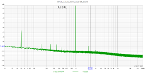
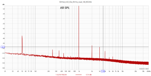
I've built it last year, and in the attachments are the spectra I measured at 2 and 6Vrms. The load was 1k8 (the input impedance of my notch filter).
In interpreting the results, the 2nd harmonic peak must be shifted down by 50dB, and the 3rd one by 54dB (the notch filter attenuation + the LNA gain of 60dB).
For example, at the output volage of 2Vrms, the 2nd harmonic is in reality at -149.3dBc, and the 3rd one at -162dBc.
One warning, though: the project uses SMD components with the size 0603, possibly not everybody's thing.
https://github.com/mpinese/electronics-uldosc
I've built it last year, and in the attachments are the spectra I measured at 2 and 6Vrms. The load was 1k8 (the input impedance of my notch filter).
In interpreting the results, the 2nd harmonic peak must be shifted down by 50dB, and the 3rd one by 54dB (the notch filter attenuation + the LNA gain of 60dB).
For example, at the output volage of 2Vrms, the 2nd harmonic is in reality at -149.3dBc, and the 3rd one at -162dBc.
One warning, though: the project uses SMD components with the size 0603, possibly not everybody's thing.
Attachments
Thank you Helmut for sharing. I have also a victor oscillator. But do not use it often. The combination DAC,ADC and software is simple and multifunctional and enough for my own reference. Just one setup for loudspeaker and (pre)amp measurements.
Hello DNi,
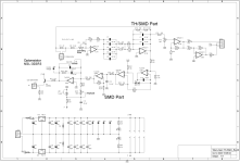
there is an identical circuit that was posted by user alfredr in his thread "Analog Filters, Notches, Amps, Attenuators and more". Same amplitude control with optoresistor NSL-32SR3. However, unlike janazcard's circuit, he has at least provided an output buffer with amplitude adjustment option, in this case a potentiometer. Here there is even a balanced output, with 100 Ohm output impedance each, so that at least a 1m long BNC cable can be driven without oscillations.
I received exactly such an oscillator from user alfredr and also measured it with a passive twin-T-notch filter. I implemented the output buffer with OPA 1656. The THD I measured was -138.80 dB at 3.171V RMS output voltage. (See also alfredr's thread). It's still very good, but 10dB worse than your measurements. It could of course be due to the board design, but alfredr is a very experienced engineer. What I noticed in my measurements on this type of oscillator, however, was the relatively mediocre THD+N value of -112dB at 3V RMS output voltage. The Bridged-T oscillators and especially the State Variable oscillators that I developed were at least 6dB better.
Kind regards
Helmut Sell
Attachments
Yes. You can PM me.Is Victor still selling his oscillator? Anyone have a link or info?
Vic.
Hello Helmut,
You're right, the noise floor of the GitHub oscillator could've been reduced, at least by increasing the capacity in the NFB to the largest FKP2 capacitor (33nF).
On the other hand, an oscillator for use in the THD measurements must simultaneously have both the distortions and the noise floor than the prospective DUT.
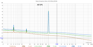
Refering to the attachment, the uppermost spectrum shows the noise floor of my example of the Victor's oscillator, the middle one the same for my build of the GitHub project, and the lowest one is the noise floor of my measurement system (notch filter, 60dB LNA, and the Cosmos ADC at the 4.5V range, termed NGLNA in the curve legend). The two oscillators were both measured at 2Vrms, the load was 1.8k (the input impedance of my notch filter), and the NGLNA was measured with the input grounded.
Taking the 2nd harmonic as an example, and considering the notch filter attenuation of 10dB at 2kHz and the LNA gain of 60dB, the noise floor of the Victor's, GitHub, and NGLNA would be -158, -162.2 and -169.3dBc, respectively.
In order to be able to measure the 2nd harmonic of a DUT at the respective noise floors, the two oscillators must have their own 2nd's at the above limits or lower.
My Victor's is about right (typically, I measure the 2nd at -158dBc), but the GitHub's 2nd is in my case typically at -149dBc, which means 13dB higher than the respective noise floor.
However, it is encouraging that the GitHub even in this version has a lower noise floor than the Victor's, so it might profit from some tweaking.
You're right, the noise floor of the GitHub oscillator could've been reduced, at least by increasing the capacity in the NFB to the largest FKP2 capacitor (33nF).
On the other hand, an oscillator for use in the THD measurements must simultaneously have both the distortions and the noise floor than the prospective DUT.
Refering to the attachment, the uppermost spectrum shows the noise floor of my example of the Victor's oscillator, the middle one the same for my build of the GitHub project, and the lowest one is the noise floor of my measurement system (notch filter, 60dB LNA, and the Cosmos ADC at the 4.5V range, termed NGLNA in the curve legend). The two oscillators were both measured at 2Vrms, the load was 1.8k (the input impedance of my notch filter), and the NGLNA was measured with the input grounded.
Taking the 2nd harmonic as an example, and considering the notch filter attenuation of 10dB at 2kHz and the LNA gain of 60dB, the noise floor of the Victor's, GitHub, and NGLNA would be -158, -162.2 and -169.3dBc, respectively.
In order to be able to measure the 2nd harmonic of a DUT at the respective noise floors, the two oscillators must have their own 2nd's at the above limits or lower.
My Victor's is about right (typically, I measure the 2nd at -158dBc), but the GitHub's 2nd is in my case typically at -149dBc, which means 13dB higher than the respective noise floor.
However, it is encouraging that the GitHub even in this version has a lower noise floor than the Victor's, so it might profit from some tweaking.
Attachments
These results are quite impressive, especially the performance you have been able to get out of the HP339. I have an unmodified HP339 and its stock performance could definitely use improvement. When I was a teenager I could not afford good test equipment. My first oscillator was an EICO 377. I eventually modified it to be a fully solid-state design with much lower distortion and an extra decade of frequency range to 2 MHz. I also added a decade attenuator to its output. Later, working at Bell Labs starting in 1971, I had all the finest equipment money could buy, and learned a lot about how it worked, since back then we had really good technical manuals with the Tek and HP equipment. I used to occasionally borrow the HP3580A spectrum analyzer and take it home to make some measurements. My favorite AC voltmeter back then was the HP 400EL that was flat to 10 MHz and had a dB-linear meter movement.Hi Bob,
First of all, thank you very much for your very detailed answer. I agree with you that the QA403 is a very good and useful tool for testing power amps, etc. I bought a QA401 myself a few years ago. There was also a QA480 (analog 1kHz sine generator with twin-T notch filter). Unfortunately, I think only 25 units were built and the device is no longer available. I would pay significantly more than 250 EUR for it (price in Germany). But whatever, QA certainly had reasons for no longer producing the device.
That was also the reason why I developed the oscillators myself. I am an electrical engineer, but audio is just a hobby of mine. I will certainly never reach your skills in analog circuit technology. The project with the continuously tunable 5-stage SVO sounds very exciting...
I started building oscillators with 1kHz about 10 years ago. These were Wien bridges and then bridged-T oscillators, like the HP339A but only for 1kHz. I modified the amplitude control of the HP339A (different time constants for the integrator, etc.) and achieved a THD of around -140dB at 1kHz and 1-3V RMS output. Then I also used the state variable principle. The oscillator that I had measured with the APX555 has 4 fixed frequencies 1,2,3,5 kHz. So it is not continuously tunable. But I also built one that can be switched from 1-10kHz in 1kHz steps, with a similar performance of THD and THD+N.
In order to test my oscillators myself, I built a notch filter (state variable filter) where I can adjust the frequencies from 1kHz-20kHz in 0.5kHz steps using DIL switches. The notch filter has a Q of 1 and therefore suppresses the harmonics much less than a twin-T notch filter. An amplifier (OPA 1612) then amplifies the notch output by approx. 30dB. The attenuation at the resonance frequencies is approx. -80dB. With this filter and my R&S UPL, which then does the FFT, I can measure up to approx. -150dB THD.
Kind regards
Helmut Sell
Cheers,
Bob
Hi Bob,
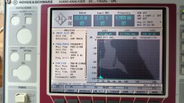
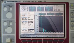
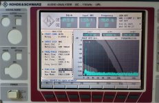
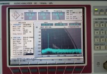
I may have expressed myself in a confusing way. I have the operating and service manual for the HP339A. There is also a circuit diagram of the oscillator. Based on this circuit diagram, I then developed my own bridged-T oscillator, which then has a THD < -140dB at 1kHz (1-3V RMS). The original HP339A obviously cannot achieve this, simply because of its age of almost 50 years. But I still have one on my workbench. I measured it again today with my audio analyzer from R&S UPL (also almost 30 years old). I haven't used the HP339A properly for 10 years. If the potentiometers and rotary switches were cleaned properly, it would definitely be a few dB better. I took 4 pictures. One THD and THD+N at 2V / 1kHz (bandwidth analyzer 22kHz). And then THD and THD+N at 2V / 20kHz (bandwidth analyzer 110kHz). The performance is pretty impressive for that time, I think. The frequency and amplitude stability of the oscillator is also impressively good.
Best regards
Helmut Sell
Attachments

- Home
- Design & Build
- Equipment & Tools
- Low-distortion Audio-range Oscillator