Wima MKS 02 with lead spacing 2.5 mm can be maximum 1µF. Not sure if that will be good for the output capacitor. The input impedans of the circuitry following it nned to be high not to cause low frequency roll-off.
Was this clarified? 10uF with the 1Meg resistor gives you 0.016Hz while 0.1uF (100nF) gives you 1.6Hz as your low 3dB point.
Great thank you! It look like 0.1uf on the input and 10uf on the output give roughly the same bandwidth. The real question is : what is the value the designer of this beautiful projet ended up using ?? 😉
Hubert
Remember the output also does see the power amplifier input impedance in parallel with the filter’s 47 kOhm.
If I can find a part with a snugger fit, it would be good.Thanks, Skip
I don't have the Gerbers but tried some leads of known diameter (and checked with caliper) . . 032" fits nicely.
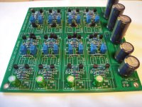
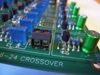
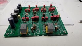
Left and Right bypass Caps marked C
The capacitors marked C on the left and right of the circuit board (see attachment) do NOT seem to be in the schematic of the crossover or power supply. They seem to bypass the power supply electrolytic.
Nelson, what is the correct value for these bypass caps ???
Capacitor left and capacitor right are in parallel with the third C-R-C-R-C ( in other words , the output of the power filter ) . The capacitors bypass the electrolytic. I plan on using film caps for input and output caps . I know I will need to use less than 10uf and pay attention to the RC time constant as this forms a high pass filter. The 221k resistor in question is in the same position as the 1Meg input resistors, supplying the Vref to the FETs onthe input buffer. I soldered in a 1 Meg resistor. Cant wait to compare this crossover to my opamp based filter.
The capacitors marked C on the left and right of the circuit board (see attachment) do NOT seem to be in the schematic of the crossover or power supply. They seem to bypass the power supply electrolytic.
Nelson, what is the correct value for these bypass caps ???
Attachments
Last edited:
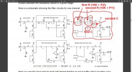
Those outlines are marked "C" and as it says in the manual; "All the values of “C” in this schematic are the same value, . . . ."
and "(C is) determined by the center frequency in the two octave range, and the “C/2” capacitors are generally at 1/2 the value of C."
and "(C is) determined by the center frequency in the two octave range, and the “C/2” capacitors are generally at 1/2 the value of C."
The capacitors marked C on the left and right of the circuit board (see attachment) do NOT seem to be in the schematic of the crossover or power supply. They seem to bypass the power supply electrolytic.
Nelson, what is the correct value for these bypass caps ???
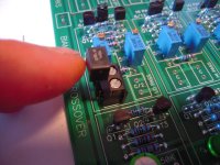
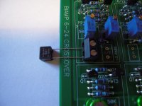
I have some nice small blue plastic 1uF/63V capacitors laying around, so I popped in two of those. They look pretty, and I believe will work well enough.
The capacitors marked C on the left and right of the circuit board (see attachment) do NOT seem to be in the schematic of the crossover or power supply. They seem to bypass the power supply electrolytic.
Nelson, what is the correct value for these bypass caps ???
A few days ago:
Capacitor left and capacitor right are in parallel with the third C-R-C-R-C ( in other words , the output of the power filter ) . The capacitors bypass the electrolytic.
I think something like 0.1µF or larger will be fine.
6-24XO
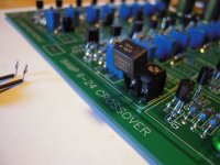
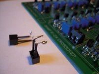
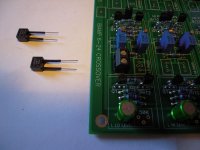
This is my approach to make tha caps for the filters changeable -
screwterminals.
Bend or prolong the legs of the small caps, solderblop and you can screw them in. It's a tight fit. But possible. 😕😀
Greets
Dirk
This is my approach to make tha caps for the filters changeable -
screwterminals.
Bend or prolong the legs of the small caps, solderblop and you can screw them in. It's a tight fit. But possible. 😕😀
Greets
Dirk
Attachments
-
 6-24XO_screwterminal_for_caps7.jpg109.6 KB · Views: 559
 -
 6-24XO_screwterminal_for_caps6.jpg93.7 KB · Views: 527
 -
 6-24XO_screwterminal_for_caps5.jpg77.7 KB · Views: 509
 -
 6-24XO_screwterminal_for_caps4.jpg85.5 KB · Views: 873
 -
 6-24XO_screwterminal_for_caps3.jpg96 KB · Views: 955
 -
 6-24XO_screwterminal_for_caps2.jpg97.5 KB · Views: 954
 -
 6-24XO_screwterminal_for_caps.jpg93.5 KB · Views: 985

Thanks Dirk, good idea! Did you figure out the C values? Or diy you keep the same values as on the screenshot you posted earlier on?
to Robin De Wolf #215 and all other builders
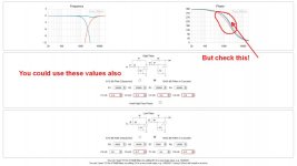
Till now I only played with the values in the simulator of Michael Rothacher.
I am focused on a 24dB crossover characteristic (steep slope).
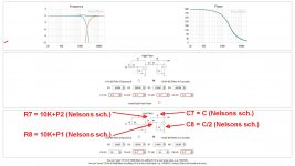
I compared the schematic in the article of Nelson Pass with the schematic in
the Simulator of M. Rothacher.
I attach some screenshots.
You can play with the values of the C's in the simulator.
I am not 100% sure which values I wanna use yet (the C's).
I changed the values of the resistors (original 10kOhm) to 4.7kOhm (in the low pass filter) and from 10kOhm in the high pass filter from 10kOhm to 6.8kOhm. Because they are always in line with the pots.Still enough adjustment range with the 50kOhm-pots.
Please be patient with me.😉 I will report back as soon as I have a result for me.
All is only simulated yet. Listening tests have to proof the simulations.
Also pay attention if you play in the simulator what your phase-shift is doing.
Greets
Dirk
Till now I only played with the values in the simulator of Michael Rothacher.
I am focused on a 24dB crossover characteristic (steep slope).
I compared the schematic in the article of Nelson Pass with the schematic in
the Simulator of M. Rothacher.
I attach some screenshots.
You can play with the values of the C's in the simulator.
I am not 100% sure which values I wanna use yet (the C's).
I changed the values of the resistors (original 10kOhm) to 4.7kOhm (in the low pass filter) and from 10kOhm in the high pass filter from 10kOhm to 6.8kOhm. Because they are always in line with the pots.Still enough adjustment range with the 50kOhm-pots.
Please be patient with me.😉 I will report back as soon as I have a result for me.
All is only simulated yet. Listening tests have to proof the simulations.
Also pay attention if you play in the simulator what your phase-shift is doing.
Greets
Dirk
Attachments
This is a little premature since I've yet to build my board. With four pots per filter section where does one start? I would keep both left and right low/high pass settings the same for a start. I also have REW and a calibrated mic. This could lead to measurement mania?😱
Regards,
Dan
Regards,
Dan
- Home
- Amplifiers
- Pass Labs
- DIY biamp 6-24 crossover