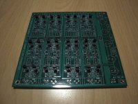
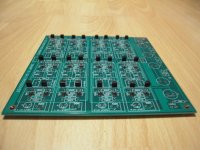
I am just received my four PCBs for this much anticipated project. Thank you, Nelson!!
I run a fully balanced system and would prefer to avoid the extra circuitry that converting/re-converting balanced to single ended and vice versa requires at the input and output of this unit. However, I am then faced with keeping each of the potentiometers across the normal and inverted “channels“ perfectly agreeing with each other. Highly impractical, of course. The alternative is 10 stereo potentiometers – an expensive and bulky proposition to have 10 ALPS pots in the box! While I could always remove them after testing and replace with fixed resistors, it seems so conceptually unwieldy.
Does anyone have a better idea?
I suppose I could also build the unit in single-ended mode as it is designed for and run my preamp to amplifiers that way during the testing process and once I have my values for the potentiometers I could then rebuild the unit for a balanced operation with fixed resistors.
Thoughts?
I decided to build in single ended initially, for simplicity. But have a plan to run voltage/resistance test points to case-mounted fixture to make it easier to match trimpots with DMM. Each board of a balanced pair can be tested one at a time single ended, then combine once they match. Would be very helpful to hear from "wise ones" on this.
I am then faced with keeping each of the potentiometers across the normal and inverted “channels“ perfectly agreeing with each other.
Nobody said they have to be perfect. Nominal matching of levels, say
10%, will still provide good noise rejection, and there are no distortion
issues to speak of.

For practical reasons it is better to start with the resistors, as these are the lowest.
For electrical reasons I would solder the trannies last, to avoid too much heat into them. (But I seriously doubt the latter to be problematic.)
For electrical reasons I would solder the trannies last, to avoid too much heat into them. (But I seriously doubt the latter to be problematic.)
matching pot values for balanced operation
...always learning from the Master. I didn't know that. Thank you, Nelson!
Nobody said they have to be perfect. Nominal matching of levels, say
10%, will still provide good noise rejection, and there are no distortion
issues to speak of.
...always learning from the Master. I didn't know that. Thank you, Nelson!

I just ordered a board 🙂 Looking forward to see if I can make something rewarding out of it! What I couldn't figure out from the manual is if there is any logic to doing frequency adjustments on each of the two pots of the two stage per low or high pass. Do you adjust these in a specific order to adjust the (steepness of a) curve?
I suggest you play with Mike Rothacher's calculator posted previously on this
thread (top of this page). It should give you some insight with regards to the
"Q" or sharpness of a filter versus some of the potential pot settings. There is
not a specific order of adjustment as such.
thread (top of this page). It should give you some insight with regards to the
"Q" or sharpness of a filter versus some of the potential pot settings. There is
not a specific order of adjustment as such.
I think this (221kOhm) should be 1MegOhm? Or am I wrong?
Greets
Dirk
Well there's no 221K on the BOM so my guess it's probably just a leftover from earlier in the design process.
Received my board today ! 😀
Question : There seem to be a little contradiction between the schematic and the silkscreen on the pcb. The input cap on the schematic is a .1uf but is a 10uf on the board and on the bom??
Second question, what value should we use for the additional filtering caps on the pcb. Those that are on each side of the filtering sections.
Merci !
Hubert
I’m trying to set this up as a high pass filter for bookshelf speakers and straight through for low pass stereo subs.
If I want to high pass at 60hz 12db, how do I calculate that?
For low pass, is it possible to just have a pass through so I can use my electronic filters within my subs?
Thanks,
Billy
If I want to high pass at 60hz 12db, how do I calculate that?
For low pass, is it possible to just have a pass through so I can use my electronic filters within my subs?
Thanks,
Billy
Received my board today ! 😀
Question : There seem to be a little contradiction between the schematic and the silkscreen on the pcb. The input cap on the schematic is a .1uf but is a 10uf on the board and on the bom??
Second question, what value should we use for the additional filtering caps on the pcb. Those that are on each side of the filtering sections.
Merci !
Hubert
1. Strange about the input cap.
2. You mean C, Left and right?
I’m trying to set this up as a high pass filter for bookshelf speakers and straight through for low pass stereo subs.
If I want to high pass at 60hz 12db, how do I calculate that?
For low pass, is it possible to just have a pass through so I can use my electronic filters within my subs?
Thanks,
Billy
1. What kind of slope do you want? 6/12/18/24 dB/octave, Butterworth, Linkwitz-Riley, Bessel etc. You can do them all.
2. No need for pass through, just connect directly to your subs. In other words, you will only need the high pass section of 6-24 crossover in the path.
1. Strange about the input cap.
2. You mean C, Left and right?
Those two
Attachments
One end of these capacitors seems to be connected to chassis ground.
Not sure about the resistor to ground at the input, there is one 221k and the others are 1MEG. I hope Nelson will clear this.
Not sure about the resistor to ground at the input, there is one 221k and the others are 1MEG. I hope Nelson will clear this.
Capacitor left and capacitor right are in parallel with the third C-R-C-R-C ( in other words , the output of the power filter ) . The capacitors bypass the electrolytic. I plan on using film caps for input and output caps . I know I will need to use less than 10uf and pay attention to the RC time constant as this forms a high pass filter. The 221k resistor in question is in the same position as the 1Meg input resistors, supplying the Vref to the FETs onthe input buffer. I soldered in a 1 Meg resistor. Cant wait to compare this crossover to my opamp based filter.
Thanks! I think I'm getting the hang of it.. You also mention 24db filters probably being the most popular, why is that? I will be replicating a two way speaker designed with originally passive 12db crossovers. I intend to use 12db with the analog crossover. Your remarks makes me wonder if 24db filters could be suitable as well?I suggest you play with Mike Rothacher's calculator posted previously on this
thread (top of this page). It should give you some insight with regards to the
"Q" or sharpness of a filter versus some of the potential pot settings. There is
not a specific order of adjustment as such.
A passive crossover interacts in a different way with the varying impedance of the drivers. You should try to get the same response. That use to lead to non-conform strict order filter curves, any slope may came out as necessary and that is the good point of this crossover. In most cases you will need to measure the response.
I think this (221kOhm) should be 1MegOhm? Or am I wrong?
Old artwork with error. Boards since May have 1 MEG in that spot.
- Home
- Amplifiers
- Pass Labs
- DIY biamp 6-24 crossover