Hi,I put this together as part of a revised power supply filter for the diy Sony Vfet and similar amps
to go in the diyAudio store and I have a nice pile of them ready to ship.
This circuit delays power to a relay (or relays in the case of the crossover) which connects the
audio output either to the active circuit (on state) or to ground (off state) by the Q2, R8, C7
portion of the circuit so as to avoid turn-on thump. It also will immediately turn off the output
when the voltage falls below a value set by P1.
P1 is adjusted to where this happens just below the normal operating voltage. The relay(s) have
a flyback diode, and are chosen for the supply voltage. You can parallel or series more than one
relay. The transistors are generic. In this schematic the intended supply 36 volts, but for 24 volts
you would simply reduce R7 to something like 18K.
Works like glue....
The full supply filter board will be posted more generally later.

I'm planning to build an LXmini XO with a linear regulated PSU, and I would like to add a soft start to protect the speakers.
This one from NP seems to be perfect for this project, but I have some doubts about the number of filters. A regulated power supply has its own filters, as does the LXmini, if I'm not mistaken.
Could someone with more knowledge tell me if this is a good idea?
Cheers
Hello,
... Perhaps my question is not clear or it's a dumb question, can I use a linear regulated power supply (sigma 11) + Power supply filter + LXmini crossover?
Sorry for the beginner's question !
... Perhaps my question is not clear or it's a dumb question, can I use a linear regulated power supply (sigma 11) + Power supply filter + LXmini crossover?
Sorry for the beginner's question !
I am using a linear power supply on one of my 6-24 crossovers. Not problematic at all.
I keep it always on.
And I use the double PI filter with three 1000 uF capacitors and two 10 ohms resistors.
I think the soft start belongs in the power amplifier.
But of course, you could implement a relay and the crossovers output, disconnecting for a few second at power on.
I keep it always on.
And I use the double PI filter with three 1000 uF capacitors and two 10 ohms resistors.
I think the soft start belongs in the power amplifier.
But of course, you could implement a relay and the crossovers output, disconnecting for a few second at power on.
Hi,
Thanks for the reply! I will keep it simple, I'm looking for 1A linear power supply... If at the end I will need some more filters or relays I will add them. First crossover, slopes and speakers measurement.
Cheers
Thanks for the reply! I will keep it simple, I'm looking for 1A linear power supply... If at the end I will need some more filters or relays I will add them. First crossover, slopes and speakers measurement.
Cheers
R-K Ronningstad:
"As long as you keep the coupling capacitors it should be fine"
Thanks for the advice.
Dave
"As long as you keep the coupling capacitors it should be fine"
Thanks for the advice.
Dave
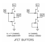
if you completely roll your own you could use the B1 Rev 1 topology for the low pass and the B1 Rev 2 topology for the high pass. Use the Toshibas for the Rev 2 and the other JFETs at the bottom end.
The low pass will send the signal through capacitors anyway.
You will ned +/-12 V for the high pass and +24 V for the low pass.
Just an idea that floated in…
The low pass will send the signal through capacitors anyway.
You will ned +/-12 V for the high pass and +24 V for the low pass.
Just an idea that floated in…
Hello,
sorry for asking something so basic. I've read this thread and the one for LXmini XO. I would like to know if the information about input and output capacitors that I find in this thread is also true for the LXmini XO. Do caps have the same function as in the 6-24 bi-amp?
sorry for asking something so basic. I've read this thread and the one for LXmini XO. I would like to know if the information about input and output capacitors that I find in this thread is also true for the LXmini XO. Do caps have the same function as in the 6-24 bi-amp?
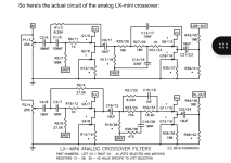
For LXmini XO leave C2/6 and C4/( as they are. C21/23 and C22/24 could bechanged to 10 uF polypropylene.
if you completely roll your own you could use the B1 Rev 1 topology for the low pass and the B1 Rev 2 topology for the high pass. Use the Toshibas for the Rev 2 and the other JFETs at the bottom end.
The low pass will send the signal through capacitors anyway.
You will ned +/-12 V for the high pass and +24 V for the low pass.
Just an idea that floated in…
Attachments
🙏"For LXmini XO leave C2/6 and C4/( as they are. C21/23 and C22/24 could bechanged to 10 uF polypropylene."
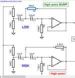
I thought C2 and C4 were for XO slopes, but please tell me if I'm wrong!
Anyway, I'm not going to use C2 because I don't need the high-pass bump. I will bypass this section of the filter, the signal from the potentiometer will go directly to C9.
I've changed C4 to 5.6 nF because my XO will be at about 2 kHz. I've used MicroCap and Vituix to simulate the frequency response. But if I'm wrong, it's good to know before I place the order.
I'm also asking about C9 and C10. They are electrolytic 10uF. Should I leave them as they are? Most likely. What capacitors can I choose from the Mouser website? Maybe I could look at Panasonic FC? Mouser doesn't have Nichicon ES 10uF.
In the article, Nelson Pass says that you can make the C21 and C22 lower to 1uF. This will limit the current when the crossover is turned on. I was thinking of using maybe a 3,3uF Wima MKP10 or Kermet. If necessary, I will add a board to connect larger capacitors.

Ah.... if I cannot change or bypass the high-pass on the lower side, this configuration will definitely not work with my Bass reflex speakers... 😏
To tell the truth, I don't quite understand why it's better not to change C3 and C4 if I need to adjust the crossover frequency. It seems to me that many people have changed the crossover points, and I’ve never read that the capacitor values shouldn’t be modified — but I’m probably wrong, because I don’t fully understand the exact effect of those capacitors on the whole circuit.

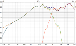
Not so different from the previous one, which is shown here with a dotted line:

PS: far-field for woofer, so no near-field and bass-reflex added.
- Anyway, if I leave them as they are, I can still modify R2 and R6 to achieve approximately the same response.
- On the Low side, I could adjust R1 and R2 to get a subsonic filter—around 20–30 Hz—without any bump. Maybe I can try bypassing this section of the filter later?

Not so different from the previous one, which is shown here with a dotted line:

PS: far-field for woofer, so no near-field and bass-reflex added.
- As for C9 and C10, I found some Nichicon ES capacitors on Mouser, which is great.
- For the output cap, I can reduce the capacitance to 1µF, as suggested by Nelson Pass, and use polypropylene (PP) caps.
Last edited:
No need to be sorry! Thank you for your support! As I don't have much knowledge in electronics, every message helps me think and understand better. It's a long journey, but I will soon place the order at Mouser. Also I am late, this thread has almost 7 years...
For example, I have read again some posts from the LXmini thread. There is someone who asked about the same thing (no need woofer eq), and avdesignguru first answered that he could simply bypass the high-pass on the lower section, but then added that it’s safer to have a high-pass at 20 Hz but without a 'bump'. So, I will start with that configuration, keeping C9 at 10 µF and C21 at 2.2 µF (Wima MKP10). Hope it works!
For example, I have read again some posts from the LXmini thread. There is someone who asked about the same thing (no need woofer eq), and avdesignguru first answered that he could simply bypass the high-pass on the lower section, but then added that it’s safer to have a high-pass at 20 Hz but without a 'bump'. So, I will start with that configuration, keeping C9 at 10 µF and C21 at 2.2 µF (Wima MKP10). Hope it works!
- Home
- Amplifiers
- Pass Labs
- DIY biamp 6-24 crossover
