Low impedance design - how low can wee go?
Following D. Self‘s recommendation I would like to minimise the filter circuit impedances for lowest noise.
But how low can we go?
- What can still be driven by the buffers without distortion increase: 5k? or even 2k?
- We still have the 1k gate stoppers. What is the minimum save value for them?
- What is the output impedance of the buffers? It should be much lower than the filter network to avoid interaction. Nelson mentioned 250Ohm for the last stage which includes 100ohm in series. I guess the impedance of the buffer itself is then 150ohm.
- What is the worst case load of the filters to the buffer? Is it the impedance of the shunt element (c/2 or P1) + the series elements assuming the caps have zero at high frequencies?
- Why is the shunt element in the high pass section (P1) referenced to Vref??? Does that limit the lowest possible value for P1?
Or in short: Can we divide the filter resistances by a factor of 5 (and increase the caps), or is that too low?
Could someone pls confirm my assumptions or correct them and let me know what you think.
Thx
Joe
I've been following this thread but might have missed it.
Have information regarding .... "with another one coming shortly"... been revealed ?
Have information regarding .... "with another one coming shortly"... been revealed ?
6-24XO
Hello members,
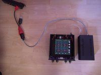
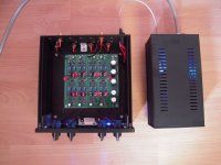
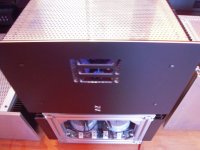
my 6-24XO is in the case (of my former ACN) and it is working - no smoke!

JFets are running at circa 36 - 40 C (temperature).
Perhaps a soundcheck this early evening....? 🙄
Greets
Dirk
Hello members,
my 6-24XO is in the case (of my former ACN) and it is working - no smoke!
JFets are running at circa 36 - 40 C (temperature).
Perhaps a soundcheck this early evening....? 🙄
Greets
Dirk
Attachments
to Joe #241
To your 4th question: This is a single ended design. V ref is in the mid (by the voltage divider in the PSU/filter section) - so around 12V (this could be described as a virtual ground. The musicsignal is swinging around the 12V (mid between 0V and 24V on the rails).
I hope I did not write nonsens? 😕
Question about the gate stoppers: Nelson also uses values around 221Ohms in certain of his designs. Here he has chosen 1kOhm.
Perhaps the master himself will chime in? 😎
Greets
Dirk
Is it possible to modify the circuit to raise its input impedance from 12k ohms?
I've got a tube preamp and will get roll-off at anything under 80k. I could change the output caps in the pre, but iterated through many options and settled on Duelund CASTs which are prohibitively expensive at the required value. I suppose I could also try to compensate within the crossover, but would prefer to start with a clean signal before modifying for the speakers.
Thanks.
increase value of input trimpot
Rin (per section) is roughly value of same, per channel - both of them (sections) in parallel
gate resistors can go low as 100R without worry about
Rin (per section) is roughly value of same, per channel - both of them (sections) in parallel
gate resistors can go low as 100R without worry about
Last edited:
6-24XO
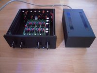
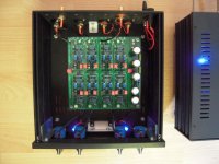
It's playing music! 😀
Preamp: B1 NUTUBE
AXO: 6-24XO
Amp (mid/bass): 50W SE Schade amp
Amp (highs): M2X
I only adjusted the inputpots of the 6-24XO. Lowpass at full power, Highs strongly reduced. Resistance of the filters have been preadjusted like in my simulations.
You can listen to music in a very satisfying way - from the start! But now starts the challenge to adjust the filters.
I am happy!!! Thanks Nelson Pass! 😎
Greets
Dirk
Attachments
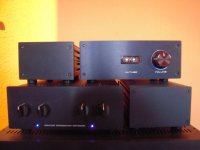
Great looking collection you have there Dirk! Enjoy the process of figuring out the x-over sweet spot[emoji6]


6-24XO
Boys (and perhaps girls), build this machine!!!
I have a cold shower going down my neck.
Details, Details in the music and control!
Gimme a beer!
Greets
Dirk
Boys (and perhaps girls), build this machine!!!
I have a cold shower going down my neck.
Details, Details in the music and control!
Gimme a beer!
Greets
Dirk
to ZenMod #249
Thanks ZenMod! A 'fugly' from you is worth a....
But I am still searching for the 1st place in dumbness....😀
Greets
Dirk
Thanks ZenMod! A 'fugly' from you is worth a....
But I am still searching for the 1st place in dumbness....😀
Greets
Dirk
.......
But I am still searching for the 1st place in dumbness....😀
Greets
Dirk
ha!
you can just dream ......
🙂
To your 4th question: This is a single ended design. V ref is in the mid (by the voltage divider in the PSU/filter section) - so around 12V (this could be described as a virtual ground. The musicsignal is swinging around the 12V (mid between 0V and 24V on the rails).
I hope I did not write nonsens? 😕
Question about the gate stoppers: Nelson also uses values around 221Ohms in certain of his designs.
HI cubicincher,
yes I think you are right, that makes sense. Thx. Interesrtingly the low pass is referenced to gnd. Here you can because of the cap.
Anyway 221R gate stoppers are ususally found in his mosfet designs.
And nice build you have done 🙂
Thanks ZM.
increase value of input trimpot
Rin (per section) is roughly value of same, per channel - both of them (sections) in parallel
gate resistors can go low as 100R without worry about
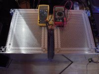
Question:
How reliable is setting filter pot resistance in situ?
I traced out connections on the board with only the leaded resistors soldered in and thought I had a reliable plan for testing and since finishing the board have been doing that by measuring Ω from far end of 10K to opposite end of its partner pot. This appears to work for both P1 and P2 in LF sections but for P1 of HF sections a stable measurement is difficult and now I distrust the whole approach. (Mostly because in listening after adjustment I'm getting some weird results.) Is there any sure fire set of points on the board for getting accurate measurements for all pots? Thanks
You can test the resistance in situ pretty accurately if you pull the various
jumpers off the board first, otherwise you will get wrong values on a
couple of the filters because other impedances are in parallel with the
thing you are trying to measure. Keep in mind that there are 10K
resistors in series with the pots, and you will have to find those spots
on the board that represent the nodes you want.
I find that I can eyeball it fairly well, after all these are linear pots and
I did mark the center resistive value on the board for reference.
I can get you high precision, but you will pay a steep price for it, but
high precision is not the point of this exercise - adjustability is.
What I want is the ability to get any values based on listening and
measurement so as to optimize the crossover for the vagaries of the
loudspeaker drivers and so on. This issue is not generally addressed
in analog products - they tend to offer only canned filter settings.

Thanks very much for your reply. No criticism from me, I completely get what you've said about the design intent.
My concern for accurate presets is only to guarantee to myself the tweeters are safe. Once I'm sure I'm in the safe zone, I'm happy to twiddle with the best of them.
The secondary advantage for me is that if I measure I get a more solid picture of where I'm starting from and thus clearer understanding of what I hear when I twiddle.
Twiddle, a word I haven't heard for a while. I like it!
Thanks again!
Boys (and perhaps girls), build this machine!!!
Greets
Dirk
Dirk, you have convinced us all 😀
.. dB
Does anyone know if the DIY Audio Store is planning a chassis for these boards that will fit the PCB mount RCA jacks and input adapter?
Thanks
Thanks
- Home
- Amplifiers
- Pass Labs
- DIY biamp 6-24 crossover