It use to be a good idea to keep the impedance as low as possible in order to reduce noise. The resistors in series preferably below 15 kOhms, forcing the values of the capacitors to be as large as possible. Of course, the acoustic frequency response of the speaker drivers mounted in the box need to be used, not the electric response of the crossover alone. The good thing is that this crossover can be set to almost any slope.
I fully agree with Roger Gustavsson,
How you set your filter slope, as well your crossover frequency strongly depends
on the loudspeaker-chassis you want to drive. There can't be a general rule how
this active crossover has to look like. There will be a lot of try and error.
But this is part of the fun we will have with this 'baby'. Nelson Pass gave us a
very versatile tool! Zen Mod would say: Swiss knife....😉
Greets
Dirk
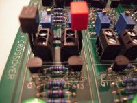
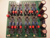
The capacitors marked C on the left and right of the circuit board (see attachment) do NOT seem to be in the schematic of the crossover or power supply. They seem to bypass the power supply electrolytic.
Nelson, what is the correct value for these bypass caps ???
Anything will work, in fact it is highly probable that no cap at all will still
be fine. For this reason I chose a value which is already on the part list.

6-24XO
Hello 6-24XO-builders,
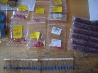
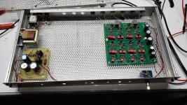
today I soldered the screwterminals in. I prolonged the legs of the WIMA-caps.
And screwed them in (low pass filter).
The story continues...
Greets
Dirk
Hello 6-24XO-builders,
today I soldered the screwterminals in. I prolonged the legs of the WIMA-caps.
And screwed them in (low pass filter).
The story continues...
Greets
Dirk
Attachments
Nice pictures - thanks for the updates
looking forward to receive my boards soon
One note though, for an experimental setup with ongoing changes it will surely work ok - but do yourself a big favor and avoid tinning any wires or component legs that you are clamping or screw mounting.
It has a negative impact on reliability and will have a better connection impedance w.o. the tinning.
It was not on purpose - but I seem to be in the footsteps of Nelson, my 6-24 Crossover will be added to a system with Pass F5 (and later F4's) and stacked ESS Heil in an open baffle system, also including SLOB's
Last edited:
Hello 6-24XO-builders,
today I soldered the screwterminals in. I prolonged the legs of the WIMA-caps.
And screwed them in (low pass filter).
There is an easier way: Digikey part 116-87-210-41-006101
which is a machined gold socket. Carve it with wire cutters and
get two sockets - the Wima 5 mm capacitors slide right in.

Got my 6-24 crossover working tonight
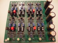
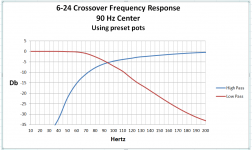
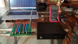
I finished up my 6-24 crossover tonight. It's working great. I preset all the pots before installing them on the board using calculated values for 90 Hz / 24 dB per octave. Attached is a graph of the frequency response I achieved with no further adjustments. Looks like I hit about 92 Hz. Not too bad. Probably will tweek it a little.
I used my DIY 24V power supply with Jung super regulator to power the crossover. (black box in the picture) This supply substantially improves my phono preamp. Don't know if will make much of a difference in this application. We'll see..
Only issue I had initially was with one of the low pass filters not working. Removing the jumper between the filter sections allowed them to be tested separately. Kind of a nice extra benefit of the jumpers. Both sections worked fine. I reinstalled the jumper and everything now works perfectly. Guess the jumper wasn't on properly. Weird.
Can't wait to listen to see how it sounds...
Thanks Nelson for a beautiful crossover !
Attachments
- but do yourself a big favor and avoid tinning any wires or component legs that you are clamping or screw mounting.
It has a negative impact on reliability and will have a better connection impedance w.o. the tinning.
Tinning and screw terminals are not a good idea, it should be avoided!
It deteriorates with time. Especially bad with mains as it may run hot and catch fire in the worst case scenario.
to #232 and#233
You are absolutely right, that the tinning and screw terminals are not the
optimal solution. But this was the price I had to pay to stay as flexible as possible.
I have something else in mind with daughter - PCBs. For the future... 🙄
Greets
Dirk
You are absolutely right, that the tinning and screw terminals are not the
optimal solution. But this was the price I had to pay to stay as flexible as possible.
I have something else in mind with daughter - PCBs. For the future... 🙄
Greets
Dirk
I think it is prohibited in mains connections here in my country. Tin is too soft and the connection can come lose.
Don't worry about it - it's actually Nørgaard, I'm not to sensitive especially not after hearing people outside DK trying to pronounce it 😉

Sorry for writing your name wrong!
Norgaard, 😉
Dirk
Question:
How reliable is setting filter pot resistance in situ?
I traced out connections on the board with only the leaded resistors soldered in and thought I had a reliable plan for testing and since finishing the board have been doing that by measuring Ω from far end of 10K to opposite end of its partner pot. This appears to work for both P1 and P2 in LF sections but for P1 of HF sections a stable measurement is difficult and now I distrust the whole approach. (Mostly because in listening after adjustment I'm getting some weird results.) Is there any sure fire set of points on the board for getting accurate measurements for all pots? Thanks
Up and running . Dead quite no hum or noise. I am biamping with a Aleph J and a 160 watt per channel class AB Fet amp for bass. Crossover is set for 24db per octave at 200hz. The difference between my opamp based crossover is quite apparent. Once again Nelson Pass hits a home run.
Attachments

- Home
- Amplifiers
- Pass Labs
- DIY biamp 6-24 crossover