You also mention 24db filters probably being the most popular, why is that? I will be replicating a two way speaker designed with originally passive 12db crossovers. I intend to use 12db with the analog crossover. Your remarks makes me wonder if 24db filters could be suitable as well?
Possibly.
24 dB Linkwitz-Riley are very popular for summing flat and minimizing
driver bandwidth issues, but are not optimal for everything. My experience
is that the best procedure is to try lots of variations and see what works
best.
Old artwork with error. Boards since May have 1 MEG in that spot.
translation:
Greedy Boy'z Braincheck point

to Nelson Pass #180
I like old and modern pieces/PCBs of art! 😀
Sometimes they are unique...
 Dirk
Dirk
I like old and modern pieces/PCBs of art! 😀
Sometimes they are unique...
DirkOk! I just got a message that the boards (also Wayne line stage) have been sent, which leaves me just enough time to set up some kind of routine on paper to go through all the possibilities.🙂
Thanks again mr. Pass for the entertainment and education along with it from the start (ACA) almost two years ago!
Thanks again mr. Pass for the entertainment and education along with it from the start (ACA) almost two years ago!
Very nice board Mr Pass! (The pic is just becuase it's an easy crack at being the first one . . . . something I don't get to do much so it's a cheap thrill at the thread's expense)
Thank you ! Everything, the layout, spacing, makes it a snap to do. Thank you!
Thank you ! Everything, the layout, spacing, makes it a snap to do. Thank you!
Attachments
C/2 is half the value of C not twice. If you're using double C then they need to be in series , not parallel.
Many thanks Papa, these boards look like a great project expecialy for those having 2 way speakers... thinking nice potential gift for a good friend of mine with brand new Klipsch 2 ways (and very simplistic Xover as I could see) and already 2 power amps.
However, at the moment in front of the the power amps there is a stereo Alps pot for motorized volume control (so just a passive pre), followed by an Y adaptator to split the signal to both power amps (and in the LS there is the usual passive Xover). That's OK given the source very low output impedance and AOP input buffers in the Class D amps to build a symmetrical signal (this is a low budget HIFI and keeping cost down is defo an issue).
To keep the existing volume control, an idea could be to insert that nice active Xover between the volume pot and the power amps. However, I am somewhat conerned about a 50k volume control... driving a 50k board entry level adjustment pot.
Does anyone know if there any other clever way to insert that board easily in this small HIFI system?
I figured out "worst case" a possibility could be to add a buffer between volume control and this active Xover board, so have a B1 like volume control, but that's adding an additional circuit stage, complexity etc. so I hope there is a clever solution 🙂
Many thanks to all for this informative thread and very special thanks to Papa for (again) a great gift for the community: argh, you are likely to get me triggered (again) for another great project I "didn't need", LOL!
What a great hobby 🙂
Enjoy music and DIY very much
Claude
to Robin De Wolf #168
Hello Robin,
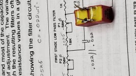
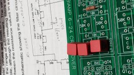
I want to use this beautiful 6-24XO for my 2-way speakers too.
My aim is to divide the frequency spectrum at 2500 Hz.
I show my values for the resistors and capacitors in the photo below.
I don't know your speakers. But many 2-way speakers are designed to
crossover anywhere between 1500 Hz and 3000 Hz (especially smaller bookshelf
speakers). The crossover frequency deopnds on the loudspeakerchassis used in your speaker.
Good high/mid dome tweeters can go low as circa 1500 Hz without any nasty
distorting sounds.
I assume that your mid/woofer in your speakers has a diameter of around 130 - 170mm (the cone without the basket).
So i would test to crossover at 2000 - 2500 Hz. Easily adjustable with this
fantastic 6-24 Xo from Nelson Pass. Also the different sound pressure levels can be easily adjusted with the pots at the input.
Don't be afraid! Try! The human ear is avery good 'test-instrument'.

Greets
Dirk
Hello Robin,
I want to use this beautiful 6-24XO for my 2-way speakers too.
My aim is to divide the frequency spectrum at 2500 Hz.
I show my values for the resistors and capacitors in the photo below.
I don't know your speakers. But many 2-way speakers are designed to
crossover anywhere between 1500 Hz and 3000 Hz (especially smaller bookshelf
speakers). The crossover frequency deopnds on the loudspeakerchassis used in your speaker.
Good high/mid dome tweeters can go low as circa 1500 Hz without any nasty
distorting sounds.
I assume that your mid/woofer in your speakers has a diameter of around 130 - 170mm (the cone without the basket).
So i would test to crossover at 2000 - 2500 Hz. Easily adjustable with this
fantastic 6-24 Xo from Nelson Pass. Also the different sound pressure levels can be easily adjusted with the pots at the input.
Don't be afraid! Try! The human ear is avery good 'test-instrument'.
Greets
Dirk
Attachments
to Robin De Wolf #168
Hello Robin;
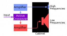
and I think you know, that your existing passive crossover in your 2-way - speaker has to be disconnected from the loudspeakerchassis. You drive each loudspeakerchassis with one channel of a power amp after the active crossover. So, for two -way - stereo speakers you need 4 poweramp channels. Two stereo poweramps.
Greets
Dirk
Hello Robin;
and I think you know, that your existing passive crossover in your 2-way - speaker has to be disconnected from the loudspeakerchassis. You drive each loudspeakerchassis with one channel of a power amp after the active crossover. So, for two -way - stereo speakers you need 4 poweramp channels. Two stereo poweramps.
Greets
Dirk

Hello Robin,
I want to use this beautiful 6-24XO for my 2-way speakers too.
My aim is to divide the frequency spectrum at 2500 Hz.
I show my values for the resistors and capacitors in the photo below.
I don't know your speakers. But many 2-way speakers are designed to
crossover anywhere between 1500 Hz and 3000 Hz (especially smaller bookshelf
speakers). The crossover frequency deopnds on the loudspeakerchassis used in your speaker.
Good high/mid dome tweeters can go low as circa 1500 Hz without any nasty
distorting sounds.
I assume that your mid/woofer in your speakers has a diameter of around 130 - 170mm (the cone without the basket).
So i would test to crossover at 2000 - 2500 Hz. Easily adjustable with this
fantastic 6-24 Xo from Nelson Pass. Also the different sound pressure levels can be easily adjusted with the pots at the input.
Don't be afraid! Try! The human ear is avery good 'test-instrument'.
Greets
Dirk
Hi Dirk, thanks for the info. I will want to try it first on my 2 way bookshelves (8 inch driver + tweeter). This morning I was putting together the bom, and still figuring what value of C and C/2 to select. In your picture it looks like you applied C times 2 instead of divided by 2?
I will be using the ACA for tweeters and F6 for midrange woofer 😉 I guess I need to get rid of the ACA thump first, afraid that it will destroy my tweeter..?
Last edited:
ACA for the tweeter and F6 for the Midwoofer sounds very good to me. 😀
I have to check if I interchanged/mixed the caps (C - C/2) in the simulation.
Have a nice weekend!
Dirk
I have to check if I interchanged/mixed the caps (C - C/2) in the simulation.
Have a nice weekend!
Dirk
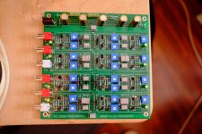
This snuck by me. Glad I finally found it. Thanks so much Nelson for this and all your contributions.
Received my board today ! 😀
Question : There seem to be a little contradiction between the schematic and the silkscreen on the pcb. The input cap on the schematic is a .1uf but is a 10uf on the board and on the bom??
Second question, what value should we use for the additional filtering caps on the pcb. Those that are on each side of the filtering sections.
Merci !
Hubert
Was this clarified? 10uF with the 1Meg resistor gives you 0.016Hz while 0.1uF (100nF) gives you 1.6Hz as your low 3dB point.
Socketing Frequency C's and Order Jumpers
I have been thinking it would make sense to have these items socketed as I suspect that these crossovers will have a life with several different applications over the years. I'd like to hear suggestions from those with more experince than I have.
Earlier this year I used the following items:
https://www.mouser.com/datasheet/2/273/4119-0-15-15-47-27-04-0-1350788.pdf
which worked, but the pins are thin relative to the PCB hole, and they were not easy to solder in squarely. Could someone with access to the Gerbers on this PCB let me know the diameter of the sandard small holes on these? If I can find a part with a snugger fit, it would be good.
Thanks, Skip

Was this clarified? 10uF with the 1Meg resistor gives you 0.016Hz while 0.1uF (100nF) gives you 1.6Hz as your low 3dB point.
I would prefer to use film caps for the input och output capacitors. Need some fiddling with wires. The PCM is only 0.1".
From Mouser you can buy the Kemet SRM5105J50J0616 1uF PPS at 5 mm lead spacing. Nice at the input.
I think the lead spacing is 2.5 mm and the diameter is 5 mm for the electrolytics. For lead spacing 5 mm, Wima MKS 2 is available up to 10µF.
- Home
- Amplifiers
- Pass Labs
- DIY biamp 6-24 crossover