legarem said:Yes the shield is there between the PS and Pre. It doesn't do anything about noise reduction.
anatech said:Hi Marc,
A "tech" ground is a seriously bad idea. Abandon it.
You may have circulating ground currents with your pre grounded, so use the ground lift. That is what it's for.
-Chris
Marc and Chris,
My point is that if you look at how the ground lift is done in the SA5.1 (ref the schematics or look at the switch on my board layout a few posts back), it only lifts the ground on the pre chassis via pin 1 of the umbilical. The chassis of the PSU is always grounded. If Marc has a shield on the umbilical that is grounded at both ends, he is tieing both chassis together, which should make the float switch basically do nothing. Other than possibly create a ground loop when it is set to ground. Try it with an ohmeter from the ground pin of the AC cord to the pre chassis. Switch from ground to float... you will probably see no difference. If I do that on mine, it is open on the float setting.
Chris (Pars)
Hi Chris,
Good point. But then again, a shield should not be connected at both ends when there is a ground wire involved also.
-Chris
Good point. But then again, a shield should not be connected at both ends when there is a ground wire involved also.
-Chris
Hi Chris,
I'd agree, the shield should be telescoping and only connected on the PSU side. I had asked Marc about that a couple of pages ago, and he said it was connected on both ends.
Chris (Pars)
I'd agree, the shield should be telescoping and only connected on the PSU side. I had asked Marc about that a couple of pages ago, and he said it was connected on both ends.
Chris (Pars)
Hi Chris,
Question for you: Is there any problem with using Faston (crimp) connectors for connecting the IEC when I get the parts in as opposed to soldering/heatshrinking those connections (just the L N and Gnd on the IEC connector)? I know its probably not the audiophile approved way to do things, but so much easier to disassemble, etc.
Thanks,
Chris
Hi Chris,
They should make a gas tight seal and for low current I don't see a problem. Possibly long term, but by then you should have made a choice. Of course since it's working you won't solder it anyway. 😉 Human nature.
Just make sure your work is in accordance with your local electrical code. Be safe. Note that your IEC connector has to be designed for faston connections.
-Chris
anatech said:Hi Chris,
They should make a gas tight seal and for low current I don't see a problem. Possibly long term, but by then you should have made a choice. Of course since it's working you won't solder it anyway. 😉 Human nature.
Just make sure your work is in accordance with your local electrical code. Be safe. Note that your IEC connector has to be designed for faston connections.
-Chris
Chris,
Yeah, should work fine. The connectors on the SS bridge for the heaters are faston tabs (stock) and that isn't a low current circuit at 1.6 amps. The only IECs I had were solder, so I ordered some Faston ones. If I have to I'll use the solder tab ones and just solder them, but having to have the transformer leads thru the IEC hole to solder them was a pain. The stock AC connector was the problem with the resistances I was seeing on the ground lead... probably could have fixed it by just putting a new plug on, but what fun is that 😀. I rewired the AC leads to the transformer with 16ga stranded from an SJOO cable piece I bought at Home Depot, and am following US color code (black-line, white-neutral and green-ground). Resistance thru the preamp ground to the plug already looks better and that is just mocked up.
Chris (Pars)
Hi Chris,
I've seen many amplifiers done with those connectors. High current connections seem to use a heavier faston connector than average.
You'll be fine. Using a connector is a smart way to lengthen a short wire a cm to the connection point. 😉
-Chris
I've seen many amplifiers done with those connectors. High current connections seem to use a heavier faston connector than average.
You'll be fine. Using a connector is a smart way to lengthen a short wire a cm to the connection point. 😉
-Chris
Hi Chris,
One other thing I forgot to mention. I took a look at the heater supply ripple looking for spikes/dips/noise as you had suggested... didn't see anything. When looking at the bridge side of the reg. protection diode, I saw a pretty clean sine wave but haven't investigated yet as to amplitude, etc. until I finish with the PSU stuff. I was down on the most sensitive V range on the scope at the time, and it went offscreen vertically. The rectifier tests fine using diode testing on my DMM. I'll have to take another look at it.
Chris
Edit: was line triggering at the time also (only way I could get it to trigger)
Hi Chris,
Feed the AC to the rectifier into a distortion analyser and look at the residual.
Also, see if you have supply components in the residual of your audio output. 60 Hz will simply be pickup from radiation, look for noise bursts at 60 and 120 Hz intervals. Trigger from your line while using a 1KHz signal source.
-Chris
Hi Chris,
Good informaton should I ever have the extreme misfortune of having to take one apart. Thanks!
So how is your's running right now?
-Chris
Good informaton should I ever have the extreme misfortune of having to take one apart. Thanks!
So how is your's running right now?
-Chris
Still in pieces, waiting for a couple of pieces 🙄
BTW, regarding my PSU board redesign, how much current does the B+ source? My guess was around 65-70mA? I never measured the drop across the 500ohm resistor (I still don't like poking things in the PSU , but getting braver). When I saw that pic of Max929s PSU spread out all over the place earlier in the thread... hehe. I'd much rather deal with the connector.
I've been playing around a bit with Duncan's PSUD. When you guys talk about chokes in tube gear, you're talking in terms of henriies, as in 2-7H or so, right (and not nano)? Like the Hammond ones, etc.? As in big physically? As in won't fit in an SA5.1?
Thanks,
Chris (Pars)
BTW, regarding my PSU board redesign, how much current does the B+ source? My guess was around 65-70mA? I never measured the drop across the 500ohm resistor (I still don't like poking things in the PSU
, but getting braver). When I saw that pic of Max929s PSU spread out all over the place earlier in the thread... hehe. I'd much rather deal with the connector.I've been playing around a bit with Duncan's PSUD. When you guys talk about chokes in tube gear, you're talking in terms of henriies, as in 2-7H or so, right (and not nano)? Like the Hammond ones, etc.? As in big physically? As in won't fit in an SA5.1?
Thanks,
Chris (Pars)
Hi Chris,
Never figured that out. I'll have a look at the manual you sent and get a worst case figure for you.
-Chris
Never figured that out. I'll have a look at the manual you sent and get a worst case figure for you.
-Chris
Hi Chris,
Went ahead and measured it... 33.2V when it stabilized, across a 525 ohm resistor, so 63.4mA. 65-70mA is what I will use. Max of around 53V, so a bit over 5 watts. Playing around with Duncan's PSUD it looks like decreasing that resistor coupled with an added resistance before the first cap to approx. equal 500 ohms or so should work well (250 + 250 or thereabouts, both 5 watt) would work well. I'm taking your advice on the first cap after looking at the 6CA4 datasheets... I ordered a 47uf 500V Cerafine ($20 at angela.com, so not too bad). I wish that 450V caps were high enough voltage (perhaps they are) because I would use Panasonic TSHA (or TSHC, whatever variant comes in 450V). These are 105 degree caps and are reasonably priced and supposedly very good.
I rewired the entire PSU (I only had 5 more wires to go on the connector anyhow, so figured WTx...). 18ga teflon spc for the HV, 20ga for everything else. The 20ga will fit thru the connector, so if I did it again, I would take the connector entirely apart and rewire it all in one shot, putting on the heatshrink after reassembling the connector. The pins fit into holes with flats on two sides in the front portion of the connector body. They are a bi&ch to get aligned the way I did it 🙄 .
Changed the routing of the wiring bundles also... stock they went around the left side as viewed from the front, crammed into the fuse holder terminals on their way to the connector. I routed everything except for the transformer wiring around the right side instead.
original
rewired
IEC
Hey Chris,
Nice work there! 😉 Good clean job.
I am very sorry. I did forget to figure out the worst case current for you.
Let me know how it works when you are all done there.
-Chris
Nice work there! 😉 Good clean job.
I am very sorry. I did forget to figure out the worst case current for you.
Let me know how it works when you are all done there.
-Chris
Hi Chris,
Thanks. I still haven't listened to it yet, just verifying some stuff (everything seems normal).
The ripple on the heaters is still 11mV or so. One thing bugs me... when I pull a couple of tubes, the heater voltage goes down. I had thought that reducing the load a bit should bring the voltage up. According to the datasheet, VO = V(ref) ( 1+R2 / R1 ) + IadjR2. Vref is 1.25V, R1 = 110 and R2 = 422 (IIRC). Vo should be 6.04V, but I'm getting 5.7V. Resistance that I get from ohming the umbilical pins 4-5 is 1.0 ohm (2 wire). When I pull tubes, it goes up until the last tube, in which case I only see the 2200uf cap across the heater lines on the tube PCB.
I tried bypassing the adj. terminal per the datasheet with a 10uf tant and put in a 1N4001 protection diode for this. No change. This is supposed to give 20dB more ripple rejection. I also tried more capacitance on the tube PCB, with no change either. The only thing I haven't tried is more capacitance before the regulator (4700uf in here, as was the stock cap). These are all new Panasonic FC caps, btw (C75, C76 and the one on the tube PCB, C301 not on schematics).
Any thoughts? Or is what I am seeing normal?
Thanks,
Chris (Pars)
Hi Chris,
The voltage goes down eh? Does your ref. pin on your heater regulator go to the same ground point? Otherwise it must be oscillating and your scope isn't picking it up.
-Chris
The voltage goes down eh? Does your ref. pin on your heater regulator go to the same ground point? Otherwise it must be oscillating and your scope isn't picking it up.
-Chris
Hi Chris,
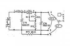
The adjust pin goes between R71 (110 ohms) and R72 (422 ohms). The attached is the SA5 schematic... the 5.1 uses an LM350K regulator. C75 is 4700uf/25V. Pin 4 (+) is tied to ground in the preamp chassis, and pin 5 is -5.7Vdc. Now that I think about it, I am measuring in the preamp chassis itself on the tube board, thru 2-3 feet of umbilical, etc., so dropping 0.3V @1.6A probably isn't too bad.
I don't think he did anything to the transformer from the 12V heaters of the SA5 (pairs of tubes in series across the heater lines. SA5.1 has each tube across the heater lines). That is a bit of voltage to be dumping across the regulator (manual shows that winding at 17VAC).
I'll have to recheck the voltage when a couple of tubes are out as the resistance across pins 4 and 5 of the umbilical goes up as expected when I pull tubes. I'm about ready to put this thing together for good and align it. I swapped out the 49.9K resistors I was using in the HV reg back to 100K/1K. Voltage across the zener is fine (48-50). I thought I found something in the heaters... I pulled all the umbilical wires from the tube board, cleaned it good, and cut them back 1/4" and resoldered. Pin 4 looked like a cold joint. Still looks the same on the scope tho. I'm guessing the ripple I'm seeing isn't anything to worry about. We'll see what my ears tell me.
Waiting for the 47uf cap to show up. I may put the other resistor in in front of it sometime in the future, looks like 150 ohms in front and replace the 500 ohm with 100 ohm (from what Duncan's PSUD is telling me).
Attachments
Hi Chris,
I was trying to alert you to look at the ground reference for your measurement. So everything is okay?
I am pretty sure you will be more than a little happy with it when you're done. You are using your new power supply PCB aren't you?
-Chris
I was trying to alert you to look at the ground reference for your measurement. So everything is okay?
I am pretty sure you will be more than a little happy with it when you're done. You are using your new power supply PCB aren't you?
-Chris
- Home
- Amplifiers
- Tubes / Valves
- Counterpoint SA 5.1