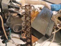
...if you have this factory version, take a close look at the tracing and breakout your volt/ohm meter and set it for continuity. What you will find is that the two red WIMA caps that are valued at 1uf 160v are in fact grounded at both ends and essentially not actively in the circuit! Both ends are grounded!!! They are just sitting there like spare tires on a car! I removed mine to make more room for air flow...
For those who are looking for them, on boards marked Rev. D, they are caps C2 and C102.
Joe
An externally hosted image should be here but it was not working when we last tested it.
Hi,
Would you please tell me the values of caps in attached image which is between resistors R18 and R30. They aren't placed on schematic.
Thanks.
Is this normal behavior?
Hey everyone, I know this thread is a bit old, but...
I recently acquired a Counterpoint SA-5.1, and it's lovely. But this is a little weird, is it expected behavior for the unit?
The unit has a chassis with the dials, and a separate power supply. The power supply is off, completely. But the smaller tubes inside the main chassis are still glowing.
In my world, off is off, so it strikes me as very odd they are glowing.
Is this behavior by design?
It's not capacitors draining energy, since this has been happening for 3 days.
When I decouple the power supply completely, the tubes turn off. If I couple it again, with the power button off, they glow again.
Thanks in advance for the help.
This behaviour is by design. ECC88 type tubes are supposed to withstand such abuse but it still seems idiotic. As cathode stripping is not an issue, they are probably trying to play it safe with the negative bias, which unfortunately is derived from the heaters circuit. How i hate cheapskate solutions.
Hi idfbts,
Yes, it is by design. A "feature" I completely disagree with and was actually done because the current fad at the time was for equipment that was on "24/7".
Depending on where you are, there are some things that should be done with it before a failure under the rectifier tube causes the PCB to literally burn under and around the socket. There is a series of changes I developed that extend the life of the rectifier tube, and reduce background noise. It can be a really nice preamp and I have modified many over the years.
I used to be the Canadian warranty depot for Counterpoint and have a lot of exposure to the entire line. Most products have problems with the power supply design. The worst was the SA-9 and similar top end products. They went so far in a direction that I don't know if I can really make the number of changes to make them more reliable. The SA-5000 has a long list of changes as well, but at the end of that you have an extremely good preamplifier that is reliable long term.
So, you have a good preamp there. It does have some issues that should be addressed sooner than later. Also, keep in mind that it is an old piece of equipment. The changes I have address that, so don't have it refreshed before mods because you would be duplicating work.
I would suggest that you use a power bar to turn all your source equipment on and off together. Power amplifiers should always be plugged directly into the wall outlet.
Edit: When replacing tubes, use the Electroharmonix as the preferred brand. They are quieter and the characteristics between tubes is closer than with brands not supplied by New Sensor (the distributor). They supply other branded tubes as well, but the Electroharmonix brand is the best for the money. They outperform most other more expensive brands of tubes out there. They also have low microphonics, and because the tubes are not run in feedback type circuits (they are run"wide open"), all noise sources are very important to reduce.
I am not a stocking dealer for them, and I usually have my customers buy them directly to avoid me marking them up, so I don't make a penny from tube sales as a rule. But I do want the best performance from my work.
-Chris
Hi. I´m also hoping that I can get a response from quite an old thread. I´ve now been in quarantine for six weeks and have decided to try to get my sa 5.1 up and running. It had all the switches the two line tubes and the volume control replaced by a technician a couple of years ago and a few months later a crackling sound started coming from the left channel. When I opened it up there was alot of flux all over the main and power supply board, and I found what I think is R60 to have been burnt. I also noticed that the solder pads for the two 5W 10kOhm resistors were quite dark and oxidized. After sifting through this thread I decided to replaced the 6ca4 and the burned resistor, have given the board a good cleaning with circuit board cleaner and then measured the voltage across CR1/D3 as a reference. Chris (anatech) said in a very early reply that it should read 45VDC and I found 97VDC. I can read a schematic reasonably well, am good with a soldering iron and have a decent multimeter but that´s about the extent of it. I´d like to try and get it working on my own seeing as it will probably be a couple of months before the Spanish govenment will allow me to drive to the technicians house.
Just as a footnote, when I first powered it up a couple of days ago there was some sparks coming from the 6gc5 and in the area around the 499ohm resitors that feed into or from the 200uF 250v capacitors. The voltage check I did afterwards was with the tubes removed.
Just as a footnote, when I first powered it up a couple of days ago there was some sparks coming from the 6gc5 and in the area around the 499ohm resitors that feed into or from the 200uF 250v capacitors. The voltage check I did afterwards was with the tubes removed.
Last edited:
Hi violagran,
I hate messy technicians!!!
Remove the 6CA4, then remove the tube socket. The two heater lines tend to short to the B+, so cut those near the pads where the feed comes from the transformer and also near the heater pins. Install two wires to make those connections and reinstall the socket and 6CA4.
Problems in the HV regulator are beyond what you can do. You should really have a Counterpoint technician do this, but if your technician really knows what he is doing, he should be able to sort it out. It doesn't sound like he knows what he is doing though.
-Chris
Thanks Chris. I´d like to hope that he knows what he is doing because he´s my only possibility apart from packing it in my suitcase and taking it to you personally next time I´m back in Canada. The excesive amounts of flux (and solder) seem to be from when the unit was made and I don´t think I can fault him for the state it´s in now because it was working fine when he returned it to me. I´ll sort out the regulator socket this morning. Are there any other places I could look if the problem continues? Thanks again.
I have the 6CA4 socket out and see the orange and white 6.3v heater leads which have a splice about 4cm after leaving the transformer ( as do all transformer leads). Should I undo the splice and solder a new lead directly to the pad?
Hi violagran,
Okay, if he is neat, my faith is restored.
You should see where the heater traces have been cut on the board. If they aren't, make sure you cut them leaving wide areas of removed copper. Then you can solder the wires directly to the pads.
Someone removed or replaced the transformer and was lazy. Examine the splices to make certain they are soldered. Use heat shrink tubing to insulate them. I hate seeing work like that too.
I'd hate to have you bring it all the way here for repair, but having said that , I have redesigned the power supply for improved performance and reliability. The only catch is that I have to do the work.
Have a good look around the regulator circuit and the pass tube. These do have a design defect that can cause what you ran into, but there is an adjustment to compensate for line voltage. Your tech needs to do that. You change a resistor to adjust the voltage drop across the current source diode. It is in parallel with a 91 V zener. If that conducts, expect damage.
When are you coming home to Canada?
-Chris
Hi violagran,
It isn't necessary, but it wouldn't hurt to measure those points either. The DC output from the regulator would be important.
-Chris
It isn't necessary, but it wouldn't hurt to measure those points either. The DC output from the regulator would be important.
-Chris
I should have been there a few weeks ago. I'd bought a flight due to a family emergency which was cancelled due to the state of emergency here. God only knows when I'll be able to get over there. Sorry to be a bit dense but are you referring to the white leads (they are all white) going from pins 4 and 5 to the socket on the back? I should solder a new lead from the solder pads on the circuit board to the umbilical socket? To bring the whole preamp to you would be a bit tricky but the power supply alone could be done and my family doesn't live far from Georgetown. One last thing I forgot to mention is that someone whom I later found to be a real hack rewired the secondaries for 220v. This unit was purchased in California in the early 80s.
My names Donald. Should have said that before. And it would be a pleasure to be able to meet you after reading thousands of your posts.
Here I am again over two years later. The technician I left it with in 2020 just gave it back to me and did nothing to it. The problem is the voltage before CR1 which was 97v and not stable. After reading through this thread, Im starting with the power supply to see if it has been wired correctly. The wire connector used to replace the ac cable is the first thing I don´t like. I would also like to ask for help to make sure that the transformer has been wired correctly for 220v. If you are reading this Chris, C77 that you metioned should be 47uF instead of 100uF is two 60uF capacitors in parallel in my unit. Thanks for you offer two years ago but I don´t think I´ll ever be able to get it over to you in Georgetown.
Attachments

No problem!
Yes, the input filters are far too large. A common design error in the "high end" crowd.
I had to completely redesign the power supplies on all the Counterpoint preamps. So I am not really surprised your tech didn't get anywhere with it. Since the fix is a redesign, I can't tell you how to do it. I have to do it.
Would it at least be possible to help me confirm that the transformer was wired correctly?No problem!
Yes, the input filters are far too large. A common design error in the "high end" crowd.
I had to completely redesign the power supplies on all the Counterpoint preamps. So I am not really surprised your tech didn't get anywhere with it. Since the fix is a redesign, I can't tell you how to do it. I have to do it.
Sorry to bother you with this but it seemed to me that Max29 was able to get his working with the power supply in it´s original form.
No problem,
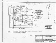
I'll try to find the transformer wiring for you. - there it is along with additional info for you.
The original supplies can be fixed, obviously they did work. They were not reliable and performance can be greatly improved.
The only thing I won't give away is many hours of work and testing, plus there are changes that are not always easy to accomplish even if I did.
Attachments
thanksNo problem,
I'll try to find the transformer wiring for you. - there it is along with additional info for you.
The original supplies can be fixed, obviously they did work. They were not reliable and performance can be greatly improved.
The only thing I won't give away is many hours of work and testing, plus there are changes that are not always easy to accomplish even if I did.
- Home
- Amplifiers
- Tubes / Valves
- Counterpoint SA 5.1