It´s me again. Sorry.No problem,
I'll try to find the transformer wiring for you. - there it is along with additional info for you.
The original supplies can be fixed, obviously they did work. They were not reliable and performance can be greatly improved.
The only thing I won't give away is many hours of work and testing, plus there are changes that are not always easy to accomplish even if I did.
I just wanted to get one thing straight from the beginning of this thread. I believe you mentioned that C77 should be changed to a 47uF or lower (40uF maybe). Both C77 and C78 are two 60uF capacitors wired in parallel which would make both 120uF I guess. Do you mean that I should replace the two 60uF capacitors of C77 with a single capacitor of 47uF/500v? The rest of your posts are very clear for me. The other thing is that my unit is a SA5 not 5.1.
Last edited:
Hi, Okay. The SA-5 and SA-5.1 are very similar. The SA-5.1 has automatic muting. They did apply production run changes during each model year
Total capacitance would b 47uF, or 40 uF. You do not need large caps and could probably use even lower values.
I would replace them if they were mine.
Total capacitance would b 47uF, or 40 uF. You do not need large caps and could probably use even lower values.
I would replace them if they were mine.
Hi Revebrator,
No problem at all.
Those are straight mechanical switches. I don't recall much in the way of logic at all. The repair person must have decided they "knew better" and modified how it works.
I would look for pictures on the internet and correct it that way. The schematic diagrams were broken up into many small (useless) sections, extremely hard to follow. This is one of those cases where I would just look at it (in the flesh) and figure it out.
You didn't say what was wrong with how they were operating.

Pretty much.
Really easy to figure out how lug type switches should be wired too. But then there is no support for the switch. As I recall, I had to order small tubes to extend the leads to the PCB (not cheap). They were like sockets for larger leads, and they soldered onto the switch leads.
Really easy to figure out how lug type switches should be wired too. But then there is no support for the switch. As I recall, I had to order small tubes to extend the leads to the PCB (not cheap). They were like sockets for larger leads, and they soldered onto the switch leads.
I am surprised they needed replacing. Hard to hit because of the knobs close by and they were C&K7000 series switches which seemed bullet proof
Hi, anatech,
I try to explain:
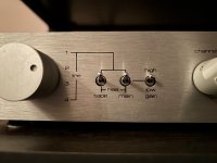
1. Use “Main” outputs, second switch in “main” position - no sound, have sound in other switch position;
2. Use 1-4 “Line” inputs and “high/low gain” switch change sound level - I think, phono section shouldn't be driving the “Line” inputs, right?
Schematic will be help, but I cannot find it, have one part only and PSU part. Maybe sombody have it all?
Cheers, Vlad.
I try to explain:
1. Use “Main” outputs, second switch in “main” position - no sound, have sound in other switch position;
2. Use 1-4 “Line” inputs and “high/low gain” switch change sound level - I think, phono section shouldn't be driving the “Line” inputs, right?
Schematic will be help, but I cannot find it, have one part only and PSU part. Maybe sombody have it all?
Cheers, Vlad.
I have had some of those switches go intermittent / noisy. Could be the industrial atmosphere in the greater Toronto areas. I have a heck of a time with the "B" series Marantz switches, and a sulphate cleaner seems to work many times.
Hi Vlad,
It sounds like the phono is shorted to the buss after the selector switch. The main switch is up for high level inputs, down for phono. The tape switch operates as you might expect (I think going from memory).
I would check the traces under the PCB. I bet someone did a cut 'n paste and got it wrong. You wouldn't need a manual for this. The fault will be obvious.
I was not precise in explanation - switches works but logic of their operation is unclear.I am surprised they needed replacing. Hard to hit because of the knobs close by and they were C&K7000 series switches which seemed bullet proof
Cheers, Vlad.
Hi Vlad,
It sounded like you were saying they operated differently after your preamp was serviced. Your explanation as to how they were operating supports that conclusion.
So ... does it work the way I explained to you?
It sounded like you were saying they operated differently after your preamp was serviced. Your explanation as to how they were operating supports that conclusion.
So ... does it work the way I explained to you?
High level inputs - do you mean 1-4 line inputs? If so, “main” switch works right.The main switch is up for high level inputs, down for phono.
I ask my master check traces.
Unfortunately, I can't say anything about the "before" switches work, I got it broken and they already tried to repair it before me.
Yes, that's correct.High level inputs - do you mean 1-4 line inputs? If so, “main” switch works right.
- Home
- Amplifiers
- Tubes / Valves
- Counterpoint SA 5.1